Planar lighting device

a lighting device and planar technology, applied in lighting support devices, lighting and heating apparatuses, instruments, etc., can solve the problems of uneven brightness, uneven brightness, uneven brightness, etc., and achieve enhanced light use efficiency, high uniform brightness, and low cost

Inactive Publication Date: 2009-02-17
FUJIFILM CORP
View PDF15 Cites 26 Cited by
  • Summary
  • Abstract
  • Description
  • Claims
  • Application Information

AI Technical Summary

Benefits of technology

[0021]Using the light guide plate described in JP 2005-234397 A, a thin, lightweight planar lighting device can be manufactured at lower costs. Further, a planar lighting device thus obtained is capable of emitting high-brightness illuminating light with enhanced light use efficiency and a highly uniform brightness, featuring a large illumination surface as well.

Problems solved by technology

If a convex portion of the rear surface of the light guide plate should come in contact with some other member and break and / or damage part of the light guide plate, this may cause unevenness in brightness.
In case of disposing reflective members to the inclined rear surfaces of the light guide plate, unevenness in brightness may also occur if the reflective members should detach from the inclined surfaces.
A light guide plate is even more liable to warp in cases where a planar lighting device is used as a backlight unit for indoor / outdoor illuminating devices, advertising signs, and the like, because in such applications, the light guide plate may be so installed that its light exit surface faces downward.

Method used


Image

  • Planar lighting device
  • Planar lighting device
  • Planar lighting device

Examples


Embodiment Construction

[0075]The planar lighting device according to the present invention will now be described in detail.

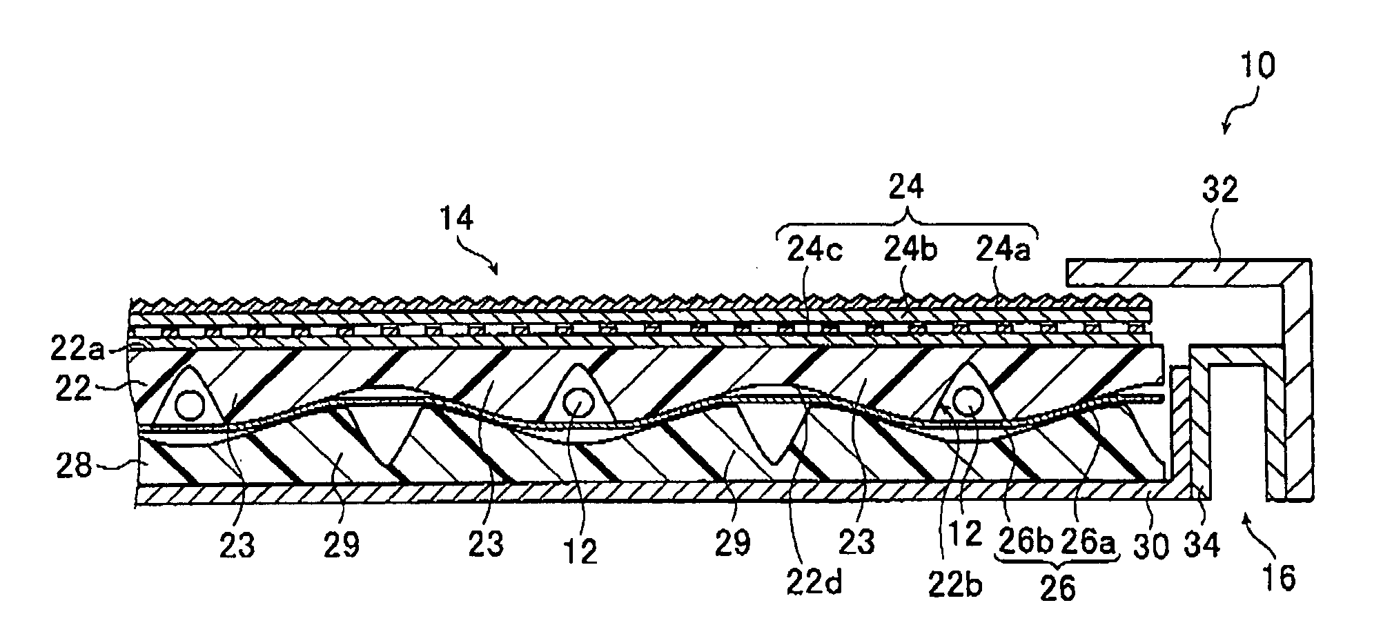
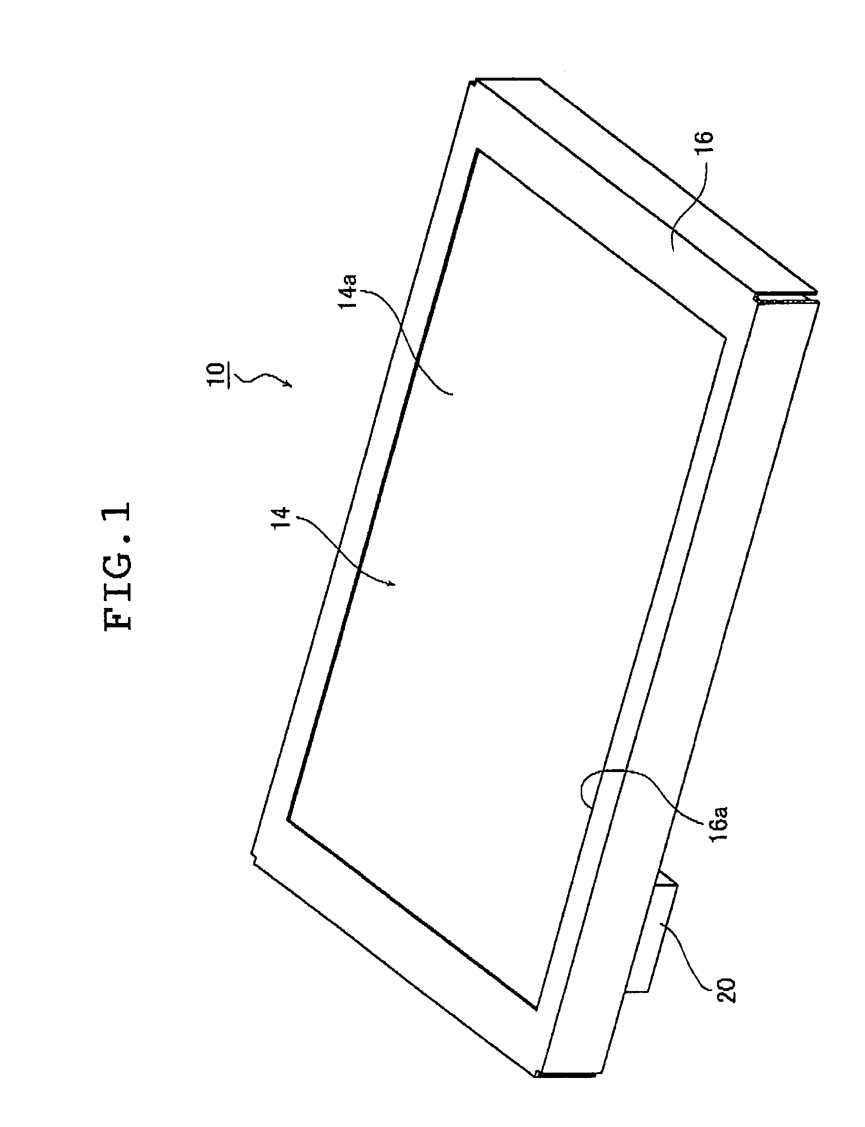
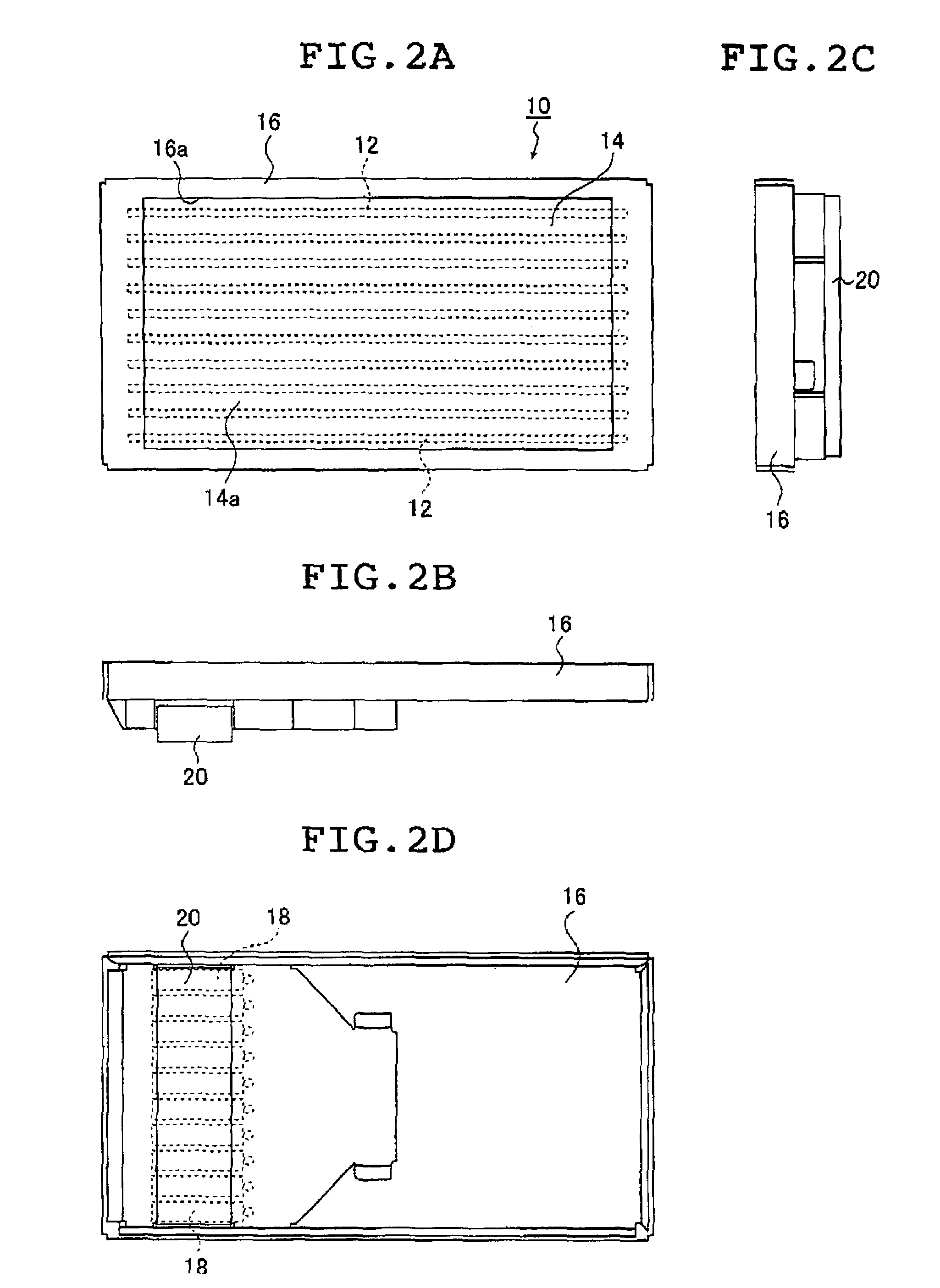
[0076]FIG. 1 is a schematic perspective view of an embodiment of the planar lighting device according to the present invention and illustrates its external appearances as seen from the light exit surface. FIGS. 2A, 2B, 2C and 2D are a top plan view, a longitudinal side view, a transverse side view, and a rear view, respectively, of the planar lighting device illustrated in FIG. 1. FIG. 3 is a partial cross-section of an embodiment of the planar lighting device illustrated in FIG. 1. These and other drawings referred to below are enlarged in a direction of thickness of the planar lighting device for ease of understanding.

[0077]As illustrated in FIG. 1 and FIGS. 2A to 2D, a planar lighting device 10 comprises a main body of lighting device 14, a housing 16, an inverter casing 20, and a power supply 38. The main body of lighting device 14 comprises linear light sources 12 and emits unifo...


PUM


Abstract

The planar lighting device includes linear light sources, a light guide plate having a flat light exit surface, a rear surface and parallel grooves formed in the rear surface for accommodating the light sources, respectively, and a support member for supporting the light guide plate with the rear surface. A cross-section of the light guide plate has a rear surface profile including convex portions having the respective grooves and concave portions formed between adjacent grooves, and a thickness in each concave portion decreases from each groove toward either midpoint between adjacent grooves and is thinnest at the midpoint. A cross-section of the support member has a first surface profile of a first surface including a profile identical to a profile of each concave portion of the rear surface profile and a second surface of the support member is a flat surface.

Description

BACKGROUND OF THE INVENTION[0001]The present invention relates to a planar lighting device used for indoor and outdoor illumination or used as a backlight for liquid crystal display panels, advertising panels, advertising towers, and other advertising signs, and comprising a light guide plate that diffuses light emitted from light sources and emits the diffused illuminating light from a light exit surface.[0002]Generally, a liquid crystal display device has a backlight unit to illuminate its liquid crystal display (LCD) panel from the rear side thereof. Currently, large-sized liquid crystal display televisions predominantly use a backlight unit of a type that comprises cold cathode tubes provided behind the rear side of a liquid crystal display panel as light sources to illuminate the liquid crystal display panel (the type will be referred to below as “direct illumination type”; see JP 05-4133 U, for example). The cold cathode tubes are arranged in a housing with white inner walls s...

Claims


Application Information

Patent Timeline
Patent Type & Authority Patents(United States)
IPC IPC(8): F21V7/04G09F13/04
CPCG02B6/0021G02B6/0031G02B6/0046G02B6/0068G02B6/0076G02F1/133605G02F1/133611G02F1/133604
Inventor IWASAKI, OSAMU
Owner FUJIFILM CORP
Why Eureka
Try Eureka