Modular terminal block

a terminal block and module technology, applied in the direction of electrical equipment, connection, coupling device connection, etc., can solve the problems of misalignment of conductors, damage to misaligned conductors, and conductors that are not accurately aligned with the vias in the circuit board, so as to reduce the deflection of conductors and accurate alignment of conductors

Active Publication Date: 2009-02-17
PHOENIX CONTACT DEVMENT & MFG
View PDF21 Cites 30 Cited by
  • Summary
  • Abstract
  • Description
  • Claims
  • Application Information

AI Technical Summary

Benefits of technology

[0011]The invention is a modular terminal block having an improved modular terminal housing. The improved terminal housing assures accurate alignment of the conductors with the vias despite manufacturing tolerance buildup along the module stack. The conductors are better supported in the housing modules to reflect reduce deflection of the conductors during installation of the circuit board. The terminal housing cover remains closed along its length after the circuit board is attached to the module stack.
[0015]The alignment member is preferably a plate having a thickness less than the distance the conductors extend out of the housing modules. The alignment plate has a number of apertures that receive the conductors and conductor positioning surfaces on the walls of the apertures. The alignment plate is movable against the modular housings to permit the conductors to extend through the plate so that the electrical component can be connected to contact portions of the conductors located above the alignment plate. The apertures preferably have enlarged openings to receive the conductors, facilitating automated installation of the alignment plate.
[0021]The modular terminal block of the present invention has a number of advantages. The modular stack can be made longer and made with more slices, with the alignment member assuring the conductors are properly located without damage for connection with the electrical body. The electrical body can be reliably installed by automated machinery, even for relatively long module stacks.
[0022]Deflection or bending of the conductors within the conductor housing during installation of the alignment member and electrical body are resisted by supporting the conductors on walls and other support members in the housing. This helps facilitate automated assembly of the alignment member and electrical body even when the module assembly includes a large number of conductors.
[0023]The cover remains reliably closed along the length of the cover after the cover is closed. Spacing the cover retention members along the length of the cover prevents gaps or bows in the cover. By having the conductors themselves form the cover retention members, no modifications to the electrical body to clear the retention members are required, and the cover member of each module assembly is held closed independently of the other cover members.

Problems solved by technology

The module stack may be made up of a relatively large number of housing modules, and tolerance buildup along the stack may cause misalignment of the conductors.
As module stacks are getting longer and longer, manufacturing tolerances may result in some conductors not accurately aligned with the vias in the circuit board.
The misaligned conductors may be damaged during insertion or may even prevent the circuit board from being installed.
As the module stacks get longer and the number of conductors increase, the deflection of the conductors makes it even more difficult to maintain proper conductor alignment during installation.
Conductors may be damaged or insertion forces may exceed acceptable levels.
As the module stacks get longer, however, the cover has a tendency to bow upward between the end plates and expose the contacts.

Method used


Image

  • Modular terminal block
  • Modular terminal block
  • Modular terminal block

Examples


Embodiment Construction

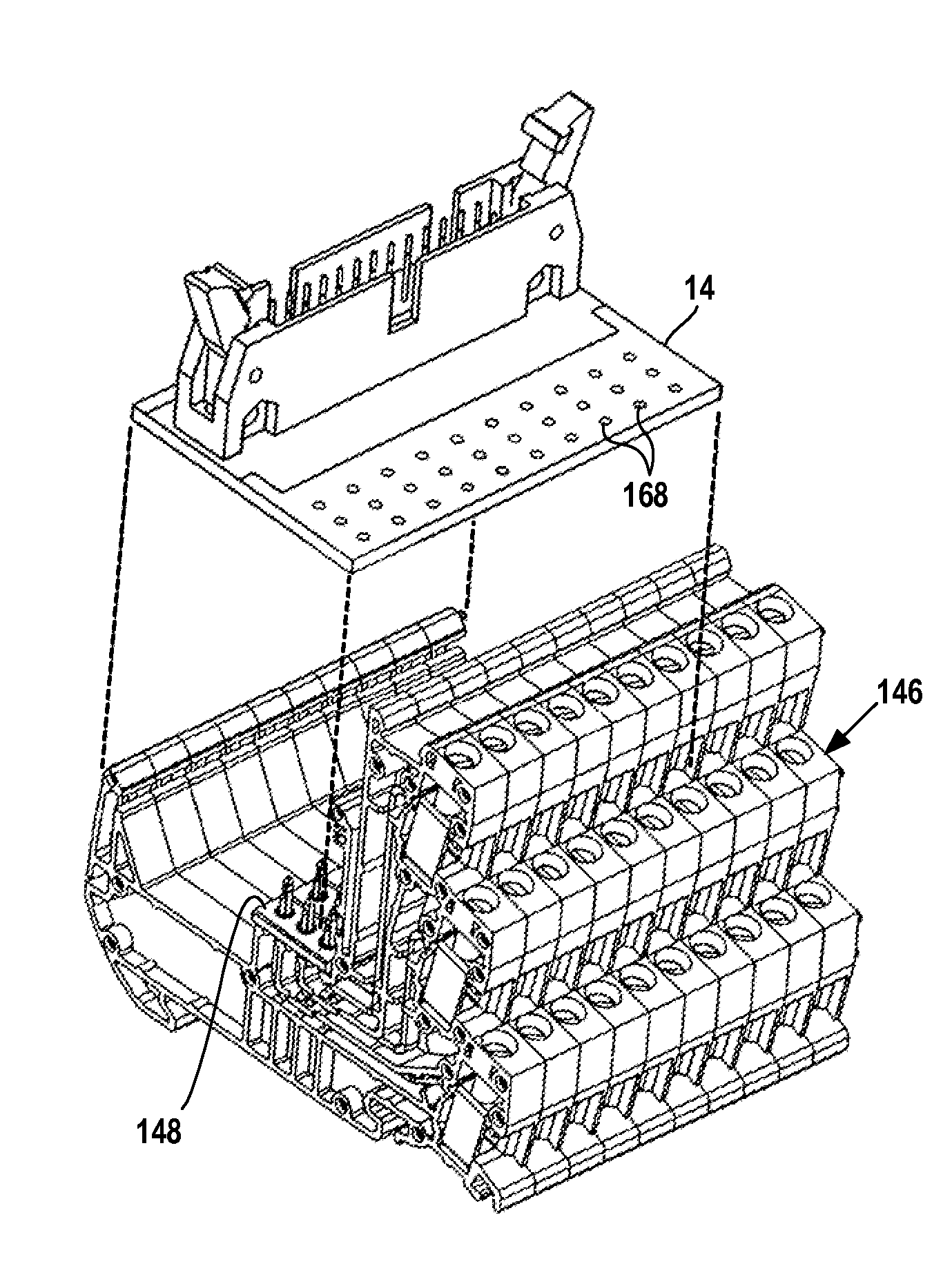
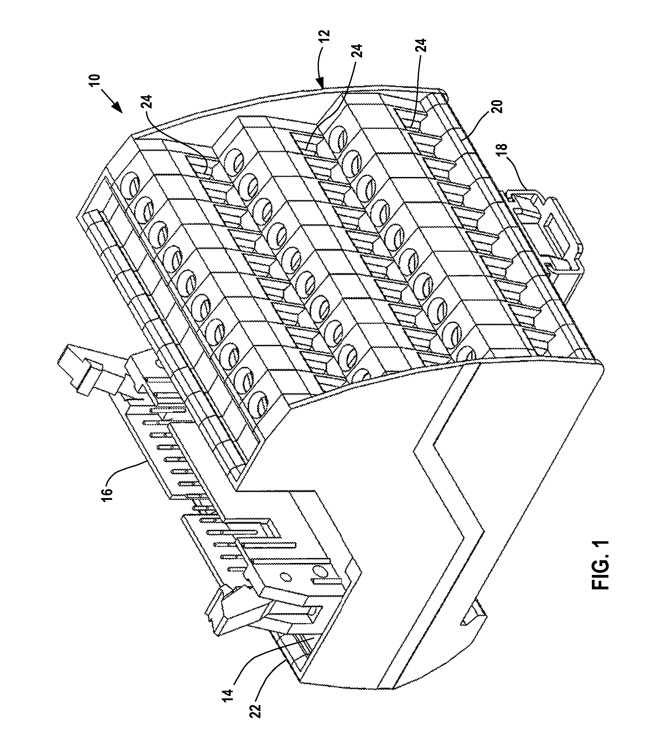
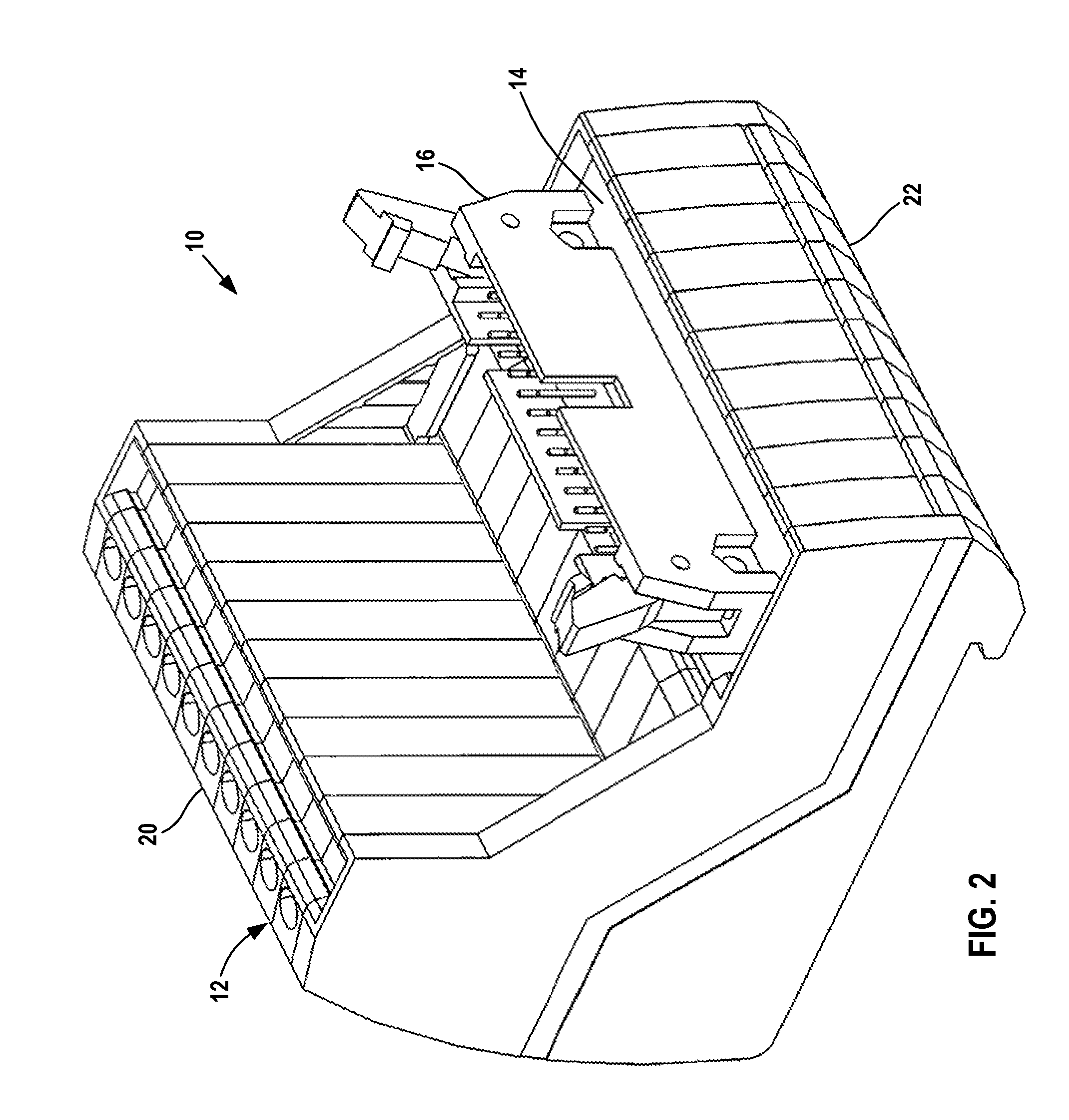
[0044]FIGS. 1 and 2 illustrate a terminal block 10 in accordance with the present invention. Terminal block 10 includes an electrical terminal housing 12 and a printed circuit board 14 permanently mounted on the housing 12. A number of electrical conductors extend from the terminal housing 12 and through a rectangular array of vias in the circuit board 14 as will be described in greater detail below. The conductors electrically connect the terminal housing 12 and the printed circuit board 14.

[0045]The printed circuit board 14 has a socket 16 for receiving an electrical component to be connected to the terminal block 10. Socket 16 is attached to a printed circuit board, but circuit boards with other types of sockets can be used with the terminal housing 12 to connect terminal block 10 to other types of electrical bodies.

[0046]Terminal block 10 is preferably configured for mounting on a conventional DIN rail and includes a DIN latch 18 for mounting the terminal block on the DIN rail.

[...


PUM


Abstract

A modular terminal block for connecting leads or wires to an electrical body includes a module stack of side-by-side module assemblies and an alignment plate. Each module assembly includes a housing, a number of conductors extending from the housing, and a cover member to cover the conductors. The alignment plate accurately positions the conductors despite variations in housing dimension due to manufacturing tolerances. The housing includes walls supported on both sides when forming part of the module stack. The walls resist deflection of the conductors during installation of the alignment plate and electrical body. Each cover member engages and is held closed by a conductor extending from the housing.

Description

FIELD OF THE INVENTION[0001]The invention relates to a terminal block for forming electrical connections between a set of wires or leads and an electrical body having an array of contacts to be connected to the set of wires or leads.BACKGROUND OF THE INVENTION[0002]Terminal blocks form electrical connections between a set of leads and an electrical body having an array of contacts. The terminal block includes a terminal housing, receptacles in the housing to receive the leads, and electrical conductors extending from the receptacles out of the housing. The exposed conductors are arranged to engage the contacts of the electrical body.[0003]Modular terminal blocks have the terminal housing formed from a module stack made of a number of like slices or housing modules. Each module contains a set of receptacles and a set of conductors. The modules are placed or stacked side-by-side, with end plates closing the ends of the module stack to form the terminal housing.[0004]The electrical bod...

Claims


Application Information

Patent Timeline
Patent Type & Authority Patents(United States)
IPC IPC(8): H01R9/26
CPCH01R9/2408H01R9/2491H01R12/7076H01R13/6658
Inventor CORRELL, MICHAEL A.
Owner PHOENIX CONTACT DEVMENT & MFG
Why Eureka
Try Eureka