Optical element, polarizing element, lighting device, and liquid crystal display

a technology of polarizing elements and optical elements, applied in the direction of polarizing elements, instruments, spectral modifiers, etc., can solve the problems of increased number of components of condensing elements, optical loss, visible surface defects, etc., and achieve enhanced brightness, convenient provision, and effective reflection

Inactive Publication Date: 2009-02-17
NITTO DENKO CORP
View PDF14 Cites 34 Cited by
  • Summary
  • Abstract
  • Description
  • Claims
  • Application Information

AI Technical Summary

Benefits of technology

[0008]It is an object of the invention to provide an optical element capable of effectively shielding transmitted lights with respect to obliquely incident lights and capable of controlling coloring.
[0032]Natural light emitted from a light source is separated by a first reflective polarizer (a1) into transmitted polarized light and reflected polarized light. The transmitted polarized light in and near the normal direction can pass through a second reflective polarizer (a1) as it is, because the retardation layer (b11) provided has a front (in the normal direction) retardation of about zero while having a retardation of at least λ / 8 with respect to incident light inclined by at least 30° to the normal direction. At angles inclined to the normal direction, the polarization state is changed by the retardation effect so that the increased polarized light components are reflected by the second reflective polarizer (a1). Particularly when the retardation is approximately λ / 2, the lights are effectively reflected. The reflected polarized lights are retarded again to have a changed polarization state in such a manner that they can pass through the first reflective polarizer (a1) and thus allowed to return to the light source unit through the first reflective polarizer. The reflected lights from the first and second reflective polarizers (a1) is depolarized by a reflective diffusing plate or the like placed under the light source, and the direction of the reflected lights is also changed by the reflective diffusing plate or the like. Part of the returning lights undergo repeated reflection until they become polarized lights in and near the normal direction, which can pass through the reflective polarizer, and thus they can contribute to an enhancement in brightness.
[0035]The optical element (a collimating film) using two pieces of such reflective polarizers (a) can form a collimating backlight, which can be thin and easily provide a highly parallel light source as compared with conventional techniques. In addition, lights can be collimated by reflection and polarization substantially without absorption loss. The reflected non-collimated components of the light are allowed to return to the backlight side and undergo cycles of scattering and reflection and selection of only collimated components of the light so that substantially high transmission rate and high light-use efficiency can be achieved.
[0037]According to the invention, therefore, there is developed an optical element, comprising: reflective polarizers (a) including at least one piece of the circular polarization type reflective polarizer (a1) and at least one piece of the linear polarization type reflective polarizer (a2); and a layer (b1) that is placed between the different types of reflective polarizers and has a front (in the normal direction) retardation of about λ / 4 and a retardation value of at least λ / 8 with respect to incident light inclined by at least 30° to the normal direction. This optical element can effectively shield transmission of light with respect to obliquely incident lights, can have good brightness properties, and can further control coloring.

Problems solved by technology

Thus, the condensing element has problems of an increased number of components, optical loss due to unnecessary scattering, and visible surface defect and visible contamination of setting gap with foreign matter.
It is difficult to achieve such a level in a conventional simple backlight system using a prism sheet or a microdot array.
In such optical elements (collimating films), however, the shielding rate is not satisfactory, and residual transmitted lights are observed with respect to obliquely incident lights.
If the width of the wavelength band to be shielded is narrow, secondary transmission can occur in oblique directions, which can lead to release and waste in oblique directions and can lead to variations in transmittance depending on wavelength so that a problem of coloring or the like can be caused in some cases.

Method used


Image

  • Optical element, polarizing element, lighting device, and liquid crystal display
  • Optical element, polarizing element, lighting device, and liquid crystal display
  • Optical element, polarizing element, lighting device, and liquid crystal display

Examples


example 1

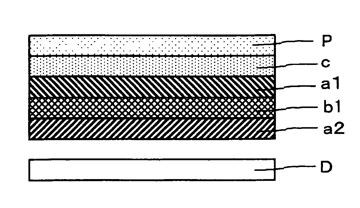
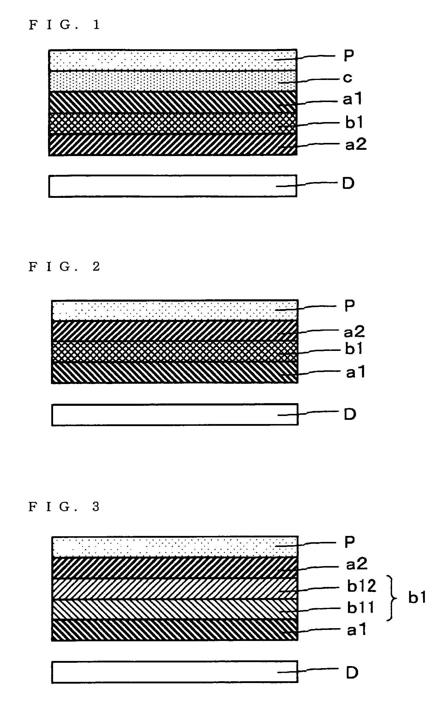
[0145]A cholesteric liquid crystal layer having a selective reflection wavelength band in the range from 410 nm to 830 nm was used as a circular polarization type reflective polarizer (a1). DBEF manufactured by 3M was used as a linear polarization type reflective polarizer (a2).

[0146]A photopolymerizable nematic liquid crystal monomer (LC242 manufactured by BASF LTD.), a chiral agent (LC756 manufactured by BASF LTD.), a photoinitiator (Irgacure 907 manufactured by Ciba Specialty Chemicals Co.), and a solvent (toluene) were prepared and mixed to form a coating liquid having a selective reflection wavelength center of 350 nm. The coating liquid was applied to a commercially available PET film with a wire bar so as to provide a post-drying coating thickness of 6 μm, and then the solvent was dried off. Thereafter, the liquid crystal monomer was once heated to its isotropic transition temperature so that the solvent was dried off. The liquid crystal monomer was then gradually cooled to f...

example 2

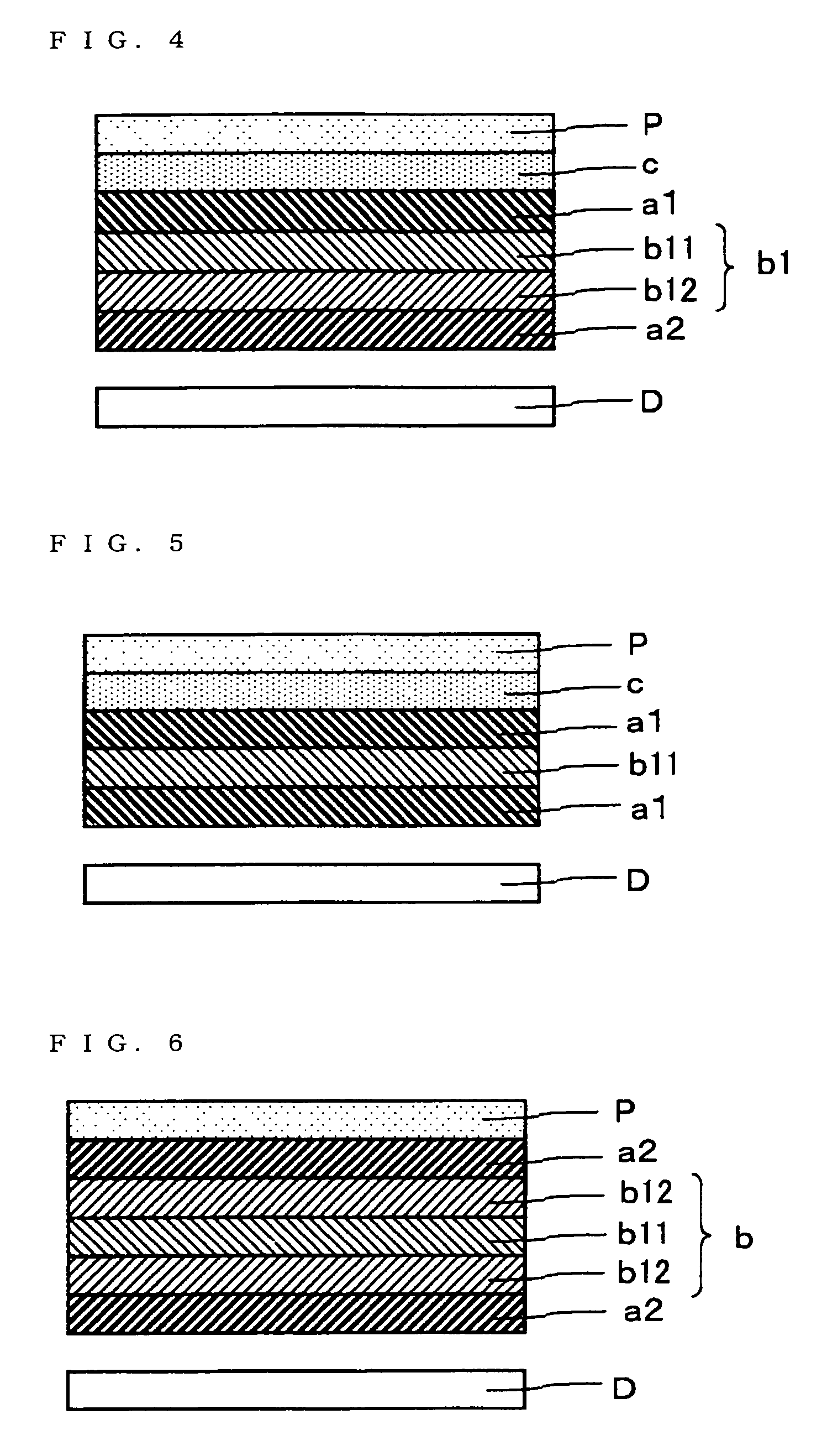
[0148]A biaxially-stretched polycarbonate film with a front retardation of 138 nm and an Nz coefficient of −1.2 was used as a quarter wavelength plate (c). The quarter wavelength plate (c) was combined with the members of Example 1 and laminated as shown in FIG. 4 to form a polarizing element. At this time, the transmission axis of the linear polarization type reflective polarizer (a2) and the slow axis of the uniaxial retardation layer (b12) were displaced by 45°.

example 3

[0149]A photopolymerizable nematic liquid crystal monomer (LC242 manufactured by BASF LTD.), a chiral agent (LC756 manufactured by BASF LTD.), a photoinitiator (Irgacure 907 manufactured by Ciba Specialty Chemicals Co.), and a solvent (toluene) were prepared and mixed to form a coating liquid having a selective reflection wavelength center of 350 nm. The coating liquid was applied with a wire bar to a PET film having a thin pre-coating of a lease treatment agent (octadecyltrimethoxysilane) so as to provide a post-drying coating thickness of 3 μm, and then the solvent was dried off. Thereafter, the liquid crystal monomer was once heated to its isotropic transition temperature so that the solvent was dried off. The liquid crystal monomer was then gradually cooled to form a layer having a uniform alignment state. The resulting film was exposed to UV so that the alignment state was fixed and a C-plate layer was formed. With respect to light with a wavelength of 550 nm, the retardation o...


PUM

PropertyMeasurementUnit
angleaaaaaaaaaa
angleaaaaaaaaaa
angleaaaaaaaaaa

Abstract

An optical element of the invention comprises at least two laminated layers of reflective polarizer; and at least one retardation layer for changing polarization properties laminated between the reflective polarizers, the combination of the layers being designed so as to provide a incident-light transmittance depending on an incident angle of an incident light and designed such that a shielded light is not absorbed but reflected. The optical element can effectively shield transmitted lights with respect to obliquely incident lights and can control coloring.

Description

TECHNICAL FIELD[0001]The invention relates to an optical element using a reflective polarizer. The invention also relates to a polarizing element, a lighting device and a liquid crystal display each using the optical element. The optical element of the invention can use diffused light from a light source at high efficiency and can form high-brightness polarized light sources and high-visibility liquid crystal displays.BACKGROUND ART[0002]Conventionally, for improvement in visibility, liquid crystal displays or the like generally use techniques for condensing emitted light into the front direction and enhancing brightness with a surface-shaped, condensing element such as a prism sheet and a lens array sheet so that the light emitted from light sources can efficiently enter the liquid crystal displays or the like.[0003]Because of the mechanism, however, such a surface-shaped, condensing element needs a large difference in refractive index for condensation of light and thus needs to be...

Claims


Application Information

Patent Timeline
Patent Type & Authority Patents(United States)
IPC IPC(8): G02B5/30G02B27/28G02F1/1335G02F1/13363
CPCG02F1/133536G02B5/3066
Inventor TAKAHASHI, NAOKITAKEDA, KENTAROUHARA, KAZUTAKASHIRAOGAWA, MIKI
Owner NITTO DENKO CORP
Why Eureka
Try Eureka