Switching power supply apparatus

Inactive Publication Date: 2009-02-17
SANKEN ELECTRIC CO LTD
View PDF15 Cites 26 Cited by
  • Summary
  • Abstract
  • Description
  • Claims
  • Application Information

AI Technical Summary

Benefits of technology

[0028]It is an object of the present invention to provide a switching power supply apparatus in which the reset time of the latch circuit is shortened by speedily discharging the electrical charge of the smoothing capacitor on the input side, and in which the actuation circuit can be inoperative at the event of abnormal overheating.Means for Solving the Problems
[0030]According to a second technical aspect of the present invention, the switching power supply apparatus further comprising a voltage detector configured to detect that the alternating-current power source is turned off based on the alternating input voltage of the alternating-current power source while the latch unit maintains the stopped state of the switching operation, wherein the actuation controller is configured to discharge the electrical charge of the smoothing capacitor when the voltage detector detects that the alternating-current power source is turned off, by applying a current having an average current larger than that of a current flown as the alternating-current power source is turned on, thereby the latch unit is speedily reset.

Problems solved by technology

However, since the voltage of the smoothing capacitor C1 is low, the capacitor C2 is not charged, and the control circuit 44 cannot resume the operation.

Method used


Image

  • Switching power supply apparatus
  • Switching power supply apparatus
  • Switching power supply apparatus

Examples


first embodiment

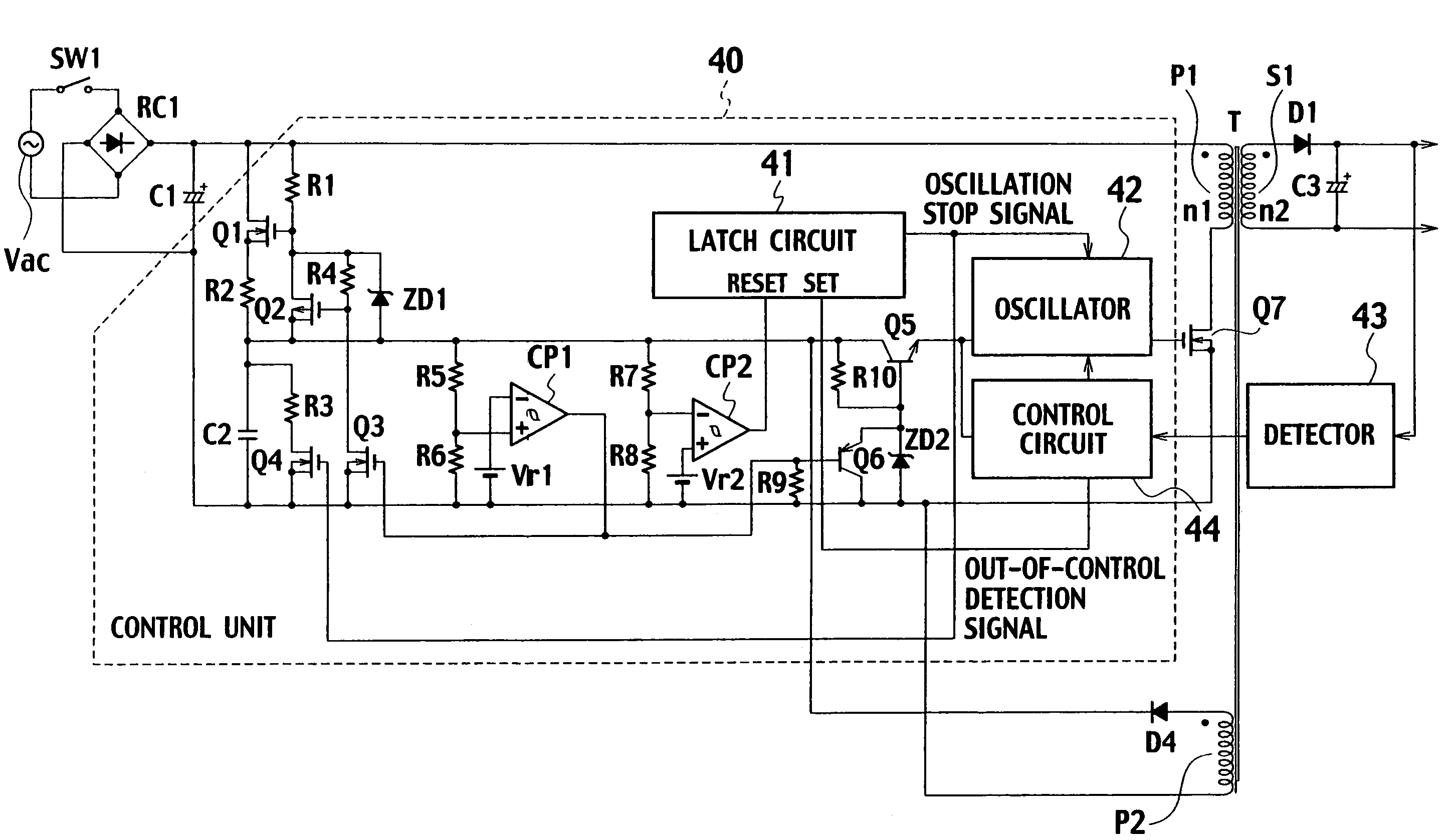
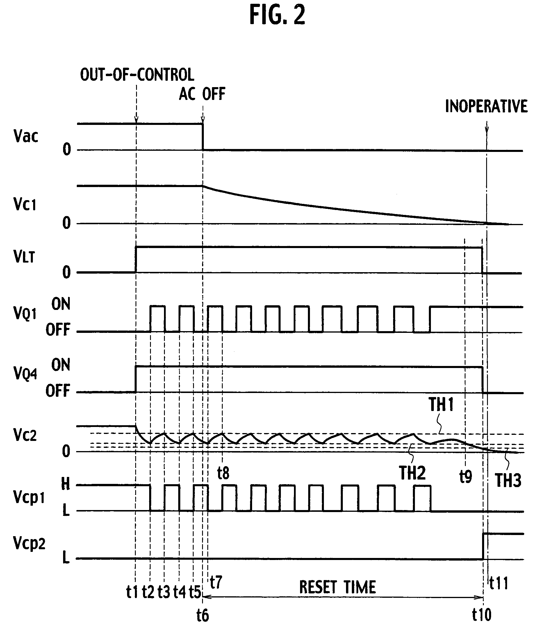
[0039]FIG. 4 is a circuit configuration diagram of a switching power supply apparatus according to a first embodiment of the present invention. In the conventional switching power supply apparatus shown in FIG. 1, for the current passing through the FET Q1, a current is set such that satisfies a function at each time of actuating, stopping, and operating the latch circuit (i.e. the time of output of the oscillation stop signal) and that does not excessively heat the FET Q1. Therefore, for the current of the FET Q1, a large current is not required, and even if the smoothing capacitor C1 is discharged by the actuation circuit when the latch circuit 41 is set to switch off the switch SW1, the reset time cannot be shortened.

[0040]In the switching power supply apparatus according to the first embodiment shown in FIG. 4, in addition to the conventional switching power supply apparatus, an overheat detector 45, an AND circuit 46, an inverter 47, NAND circuits 48, 49, and 50, a comparator C...

second embodiment

[0058]FIG. 6 is a circuit configuration diagram of a switching power supply apparatus according to a second embodiment of the present invention. In the second embodiment shown in FIG. 6, by checking an alternating input voltage, when there is no alternating current input, the FET Q1 is kept to be ON state all time, a FET Q9 is turned on, and the FET Q8 is turned on. Thus, a resistor R11 is short-circuited to increase the current passing through the actuation circuit, thereby further efficiently discharging the electrical charge of the smoothing capacitor C1, and shortening the reset time.

[0059]As shown in FIG. 6, an anode of a diode D2 is connected to one end TP1 of a full-wave rectifier circuit RC1, and an anode of a diode D3 is connected to another end TP2 of the full-wave rectifier circuit RC1. Cathodes of the diode D2 and the diode D3 are commonly connected, and this connection point is connected to one terminal of each of the resistor R13 and a capacitor C4. To a series circuit...


PUM


Abstract

There are included an actuation unit supplying an actuation power to a control unit to start a switching operation of a switching element when an alternating-current power sources turned on, and stopping supply of the actuation power to the control unit after the switching operation of the switching element is started; an overheat detection unit being thermally coupled with the actuation unit and detecting an abnormal condition due to overheating of the actuation unit; a latch maintaining an inoperative state of the switching element at the event of an abnormal condition other than the abnormal condition due to overheating of the actuation unit; and an actuation controller configured to discharge an electrical charge of a smoothing capacitor while the latch maintains the inoperative state of the switching operation to speedily reset the latch unit when the alternating-current power source is turned off, and to stop the actuation unit in response to a detection signal from the overheat detection unit.

Description

TECHNICAL FIELD[0001]The present invention relates to a switching power supply apparatus capable of shortening reset time of a latch circuit by speedily discharging an electrical charge of a smoothing capacitor.BACKGROUND ART[0002]A circuit configuration of a conventional switching power supply apparatus is shown in FIG. 1. As shown in FIG. 1, a full-wave rectifier circuit RC1 rectifies an alternating input voltage of an alternating-current power source Vac that is input through a switch SW1, and a smoothing capacitor C1 smoothes the voltage rectified by the full-wave rectifier circuit RC1 to convert into a direct voltage. To both ends of the smoothing capacitor C1, a series circuit of a primary winding P1 (the number of windings n1) of a transformer T and a switching element Q7 having a FET is connected. A control unit 40 controls a switching operation of the switching element Q7 with the direct voltage from the smoothing capacitor C1. To both ends of a secondary winding S1 (the nu...

Claims


Application Information

Patent Timeline
Patent Type & Authority Patents(United States)
IPC IPC(8): H02M3/335H02H7/122
CPCH02M1/32H02M3/335H02M3/33507H02M2001/0006H02M1/0006H02M3/28
Inventor FURUKOSHI, RYUICHIIWABUCHI, AKIO
Owner SANKEN ELECTRIC CO LTD
Why Eureka
Try Eureka