
Method for compiling and executing a parallel program

a parallel program and program technology, applied in the direction of specific program execution arrangements, program control, instruments, etc., can solve the problems of high level of knowledge and experience, complex task, compatibility, etc., and achieve the effect of reducing the complexity of tasks and complex tasks

Inactive Publication Date: 2009-02-17
UNIV DU QUEBEC CHICOUTIMI
View PDF5 Cites 42 Cited by
  • Summary
  • Abstract
  • Description
  • Claims
  • Application Information

AI Technical Summary

Benefits of technology

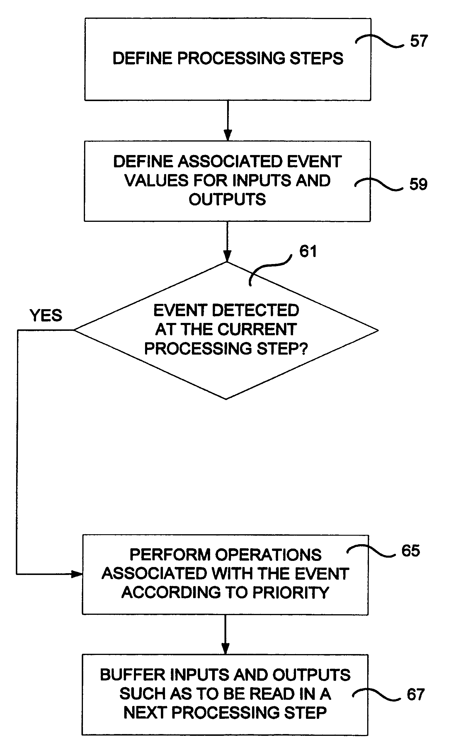
"The patent describes a method for executing machine code on a computer processor that has limited processing power. The code is designed to mimic the capabilities of a computer processor that has more processing power. The method includes defining processing steps and associated event values for each step. The operations are selectively performed based on the event values and the priority of the inputs. The results are buffered to prevent changes from being read by the inputs in a same step and copied to the next step. The code is also automatically converted into hardware programming data for real-time hardware operation. The technical effect of this patent is to provide a way to efficiently execute complex machine code on limited processing power."

Problems solved by technology

When defining code that could potentially run on sequential-type and parallel-type machines there arises a problem of compatibility.
The problem is that most programming languages are sequential and it is necessary that hardware implementation be highly parallel.
Although it is possible to translate a sequential program for parallel execution, it is a very complex task since sequential algorithms do not map easily onto parallel machines.
The drawback is that VHDL programming currently requires a high level of knowledge and experience.
The execution of the resulting programs on sequential machines is more of a simulation, and the translation of such programs for parallel hardware leads to complex results often limited to a specific class of problems.

Method used


Image

  • Method for compiling and executing a parallel program
  • Method for compiling and executing a parallel program
  • Method for compiling and executing a parallel program

Examples


example

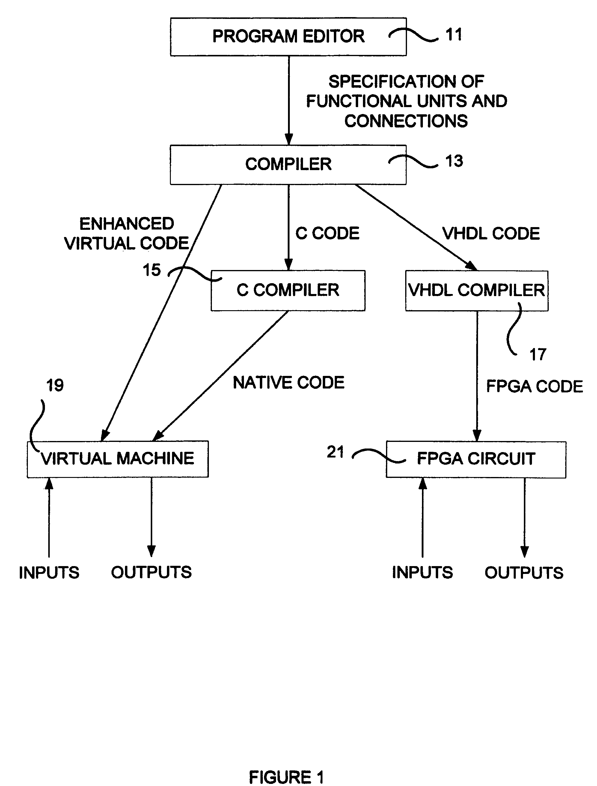
[0122]The program code listing below is used for illustrating the principles and teachings of the present invention. The listing includes a K3 program, which is a high level program code definition according to the preferred embodiment of the present invention, and the translations into C code and VHDL code performed according to the method of the present invention.

[0123]An example of a K3 program with a single component is as follows:

[0124]

component main interface  RESET : boolean (input 0);  A : int (input 1);  B : int (input 1);  C : int (input 1);  D : int (input 1);  RESULT : int (output); implementation  component Test   interface    RESET : boolean (input 0);    A : int (input 1);    B : int (input 1);    C : int (input 1);    D : int (input 1);    RESULT : int (output);   implementation    (ON 0     { RESULT = 0; } / / Assignment without event    )    (ON 1     { RESULT := RESULT + 1; } / / Assignment with event    )  end Test process  P1 : Test; communication  P1@RESULT RESULT ; ...


PUM


Abstract

A method for multi-platform parallel or real-time machine programming is provided. The method comprises specifying a parallel machine definition code defining a plurality of signal or data processing components and a communication of data or signals between the components, automatically converting the code into computer instructions for execution on an essentially sequential, non-parallel computer processor, a parallel execution of the instructions on the sequential processor and automatically converting the code into hardware programming data for providing parallel hardware operation according to the code, by including, in the hardware programming data, event control circuitry specification, priority control circuitry specification and buffering control circuitry specification to ensure that the hardware operation matches the execution on the sequential computer processor. The parallel machine code is implemented using the hardware programming data on a parallel hardware machine having parallel processing capability and using the computer instructions on the sequential processor in a manner that is essentially exchangeable.

Description

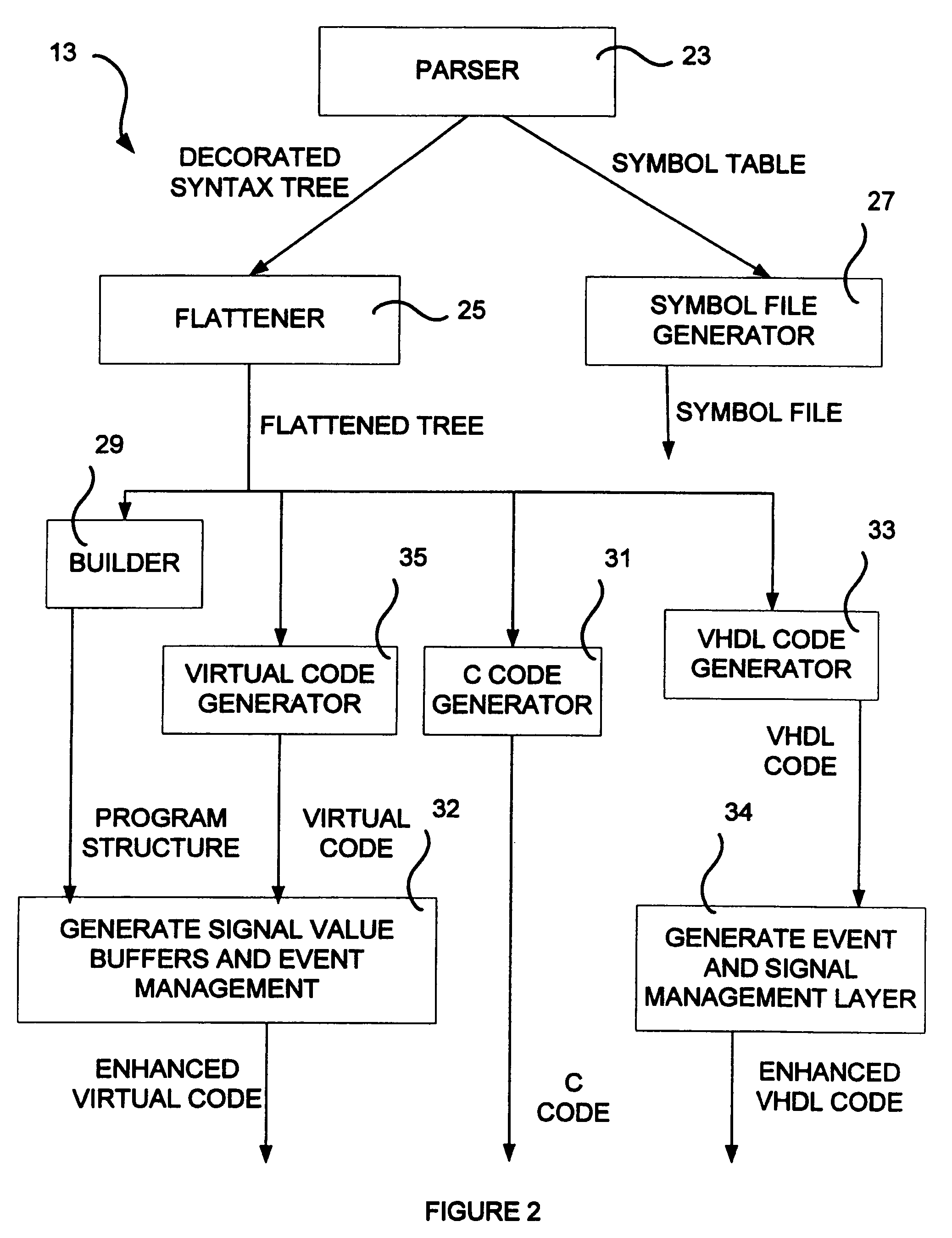
REFERENCE REGARDING A COMPUTER PROGRAM LISTING APPENDIX[0001]This application includes computer program listing appendix submitted on a compact disk which is hereby incorporated by reference. The computer program listing includes the following files:[0002]C Code directoryFIG. 2 - Flattened tree data structurebasic.hJun. 7, 200410.7 KBcir.hJun. 7, 200420.7 KBfct.hJun. 7, 20042.36 KBFIG. 3 - Compiled code interfacegenc_def.hJun. 10, 20041.61 KBgenc_fct.cJun. 8, 200422.6 KBgenc_fct.hJun. 8, 20044.06 KBgenc_macro.hJun. 8, 20042.66 KBgenc_rvm.hJun. 10, 20049.04 KBFIG. 3 - Virtual machine data structurestruc.hJun. 7, 200422.5 KBFIG. 4 - Event manager interfaceevent.hMar. 29, 20044.19 KBFIG. 4 - Virtual machine main loopboucle.cMar. 30, 20045.24 KBVHDL code directoryctype.vhdMar. 2, 20045.09 KBpackageConv.vhdJun. 17, 200423.3 KBRodinStd.vhdJun. 8, 20046.58 KB[0003]Portions of this disclosure contain material which is subject to copyright protection. The copyright owner has no objection to ...

Claims


Application Information

Patent Timeline
Patent Type & Authority Patents(United States)
IPC IPC(8): G06F9/44
CPCG06F9/4436G06F9/45504G06F17/505G06F9/4494G06F30/327
Inventor MORIN, LUC
Owner UNIV DU QUEBEC CHICOUTIMI
Learn More