Dual-chamber water jet assembly for in-ground pools or spas

a water jet and in-ground pool technology, applied in swimming pools, gymnasiums, physical therapy, etc., can solve the problems of inability to provide a good solution for an array of jets designed for use in an above-ground spa (such as ludlow's), laborious plumbing or jet installation, and inability to meet the needs of spas

Inactive Publication Date: 2009-02-24
CAP & DOLL REVOCABLE LIVING TRUST DTD 9 21 2021 JAMES MARLEN WILLIAMS & NICOLE ALEXANDRA MORRIS TTEES
View PDF21 Cites 9 Cited by
  • Summary
  • Abstract
  • Description
  • Claims
  • Application Information

AI Technical Summary

Problems solved by technology

This is because the water and air supply pipes of in-ground spas extend into the ground and through concrete reinforcing bar (“rebar”) and cementitious material (e.g., gunite), making the plumbing of multiple pipes for multiple water jets very labor intensive (see FIGS. 1 and 2).
Obviously, plumbing or jet installation mistakes are difficult and expensive to fix once the in-ground spa hardens.
Simply adding an array of jets designed for use in an above-ground spa (such as Ludlow's) would not provide a good solution due to the complexity of installation of Ludlow's hollow pod structure.
Furthermore, poor workmanship or defects in the hose materials that link each jet to the water supply line can cause leaks.
In fact, even ordinary wear and tear tends to flex hosing joints and seals and eventually open them up to form leaks.
Therefore, the more tubing or piping utilized in an array of jets, the higher the probability over time of a leak occurring.
This difference limits the number and type of water jet arrays that can usefully be installed in an above-ground spa.
Moreover, typical swimming pools have limited if any water-jet features.

Method used


Image

  • Dual-chamber water jet assembly for in-ground pools or spas
  • Dual-chamber water jet assembly for in-ground pools or spas
  • Dual-chamber water jet assembly for in-ground pools or spas

Examples


example

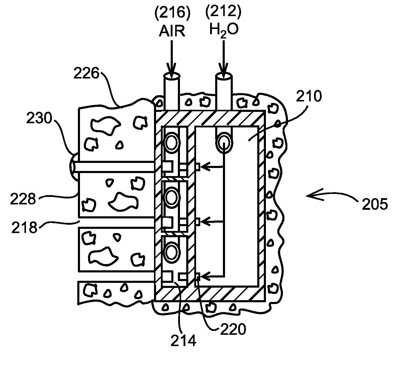
[0051]After excavation of the spa, a plumbing line from the water pump or circulation system is stubbed to the location where the array of jets will be installed. Optionally, an air line can also be stubbed to the same location. A STYROFOAM form is then placed over the capped pipe(s) to provide a hollow into which a jet array of the invention is placed after the cementitious materials are poured or sprayed.

[0052]Steel reinforcing bars are next added around the perimeter of the spa and at locations where further structural definition will take place (e.g., seats, contours, separation walls, etc.). The cementitious material is then applied to the rebar and around the STYROFOAM form to create the spa structure.

[0053]After the cementitious materials have hardened (at the preparation of the spa interior finish phase), the STYROFOAM form is removed and disposed of. The end caps of the water (and air) pipes are removed, and the inlet(s) of the array of jets of the invention are bonded to t...


PUM


Abstract

A water jet assembly for in-ground pools or spas that includes a first chamber with a water inlet and a second chamber with an air inlet and a plurality of water outlets. Water and air flow from the respective inlets to the water outlet such that a water-jet effect is achieved.

Description

REFERENCE TO RELATED APPLICATIONS[0001]This is a continuation-in-part of U.S. patent application Ser. No. 11 / 237,359, filed on Sep. 26, 2005, which is a continuation-in-part of U.S. patent application Ser. No. 10 / 889,621, filed on Jul. 12, 2004, which is a continuation-in-part of U.S. patent application Ser. No. 10 / 404,391, filed on Apr. 1, 2003, now U.S. Pat. No. 6,804,841, issued Oct. 19, 2004.BACKGROUND OF THE INVENTION[0002]1. Field of the Invention[0003]This invention relates generally to water jets for spas and the like and more particularly to apparatuses that house one or more water jets for installation in cementitious (in-ground) spas.[0004]2. Description of the Related Art[0005]Recreational bathing units, such as spas, “hot tubs,” whirlpools, swimming pools, and the like, have become increasingly popular in recent years. Many recreational bathing units are constructed as “above-ground” (as opposed to “in-ground”) models and typically include a molded shell or heavy plasti...

Claims


Application Information

Patent Timeline
Patent Type & Authority Patents(United States)
IPC IPC(8): E04H4/00
CPCA61H33/027E04H4/14A61H33/6063
Inventor WILLIAMS, JACK
Owner CAP & DOLL REVOCABLE LIVING TRUST DTD 9 21 2021 JAMES MARLEN WILLIAMS & NICOLE ALEXANDRA MORRIS TTEES
Why Eureka
Try Eureka