Low Cost Multimode Calorimeter

a multi-mode, low-cost technology, applied in the direction of measuring devices, scientific instruments, instruments, etc., can solve the problems of low adaptation typical of calorimeters available, the above-mentioned calorimeter and other prior-art calorimeters have some drawbacks, and spread of calorimetry, so as to improve the accuracy and safety of use, and improve the accuracy of the measurement. , the effect of high mechanical strength

Inactive Publication Date: 2008-10-09
CONSIGLIO NAT DELLE RICERCHE
View PDF3 Cites 9 Cited by
  • Summary
  • Abstract
  • Description
  • Claims
  • Application Information

AI Technical Summary

Benefits of technology

The invention is a calorimeter that has a strong structure and is designed to have a long life and be safe to use. It is also easy and cheap to make and can be used for a variety of industrial applications and research and education activities.

Problems solved by technology

The technical problem addressed in this patent is the need for calorimeters that have good sensitivity, precision, and can adapt to the characteristics of different samples. These calorimeters should also be easy to use in automatic measuring procedures and should be able to control industrial processes and investigate products. However, current calorimeters have limitations such as requiring qualified operators and being low in adaptation.

Method used


Image

  • Low Cost Multimode Calorimeter
  • Low Cost Multimode Calorimeter
  • Low Cost Multimode Calorimeter

Examples


Embodiment Construction

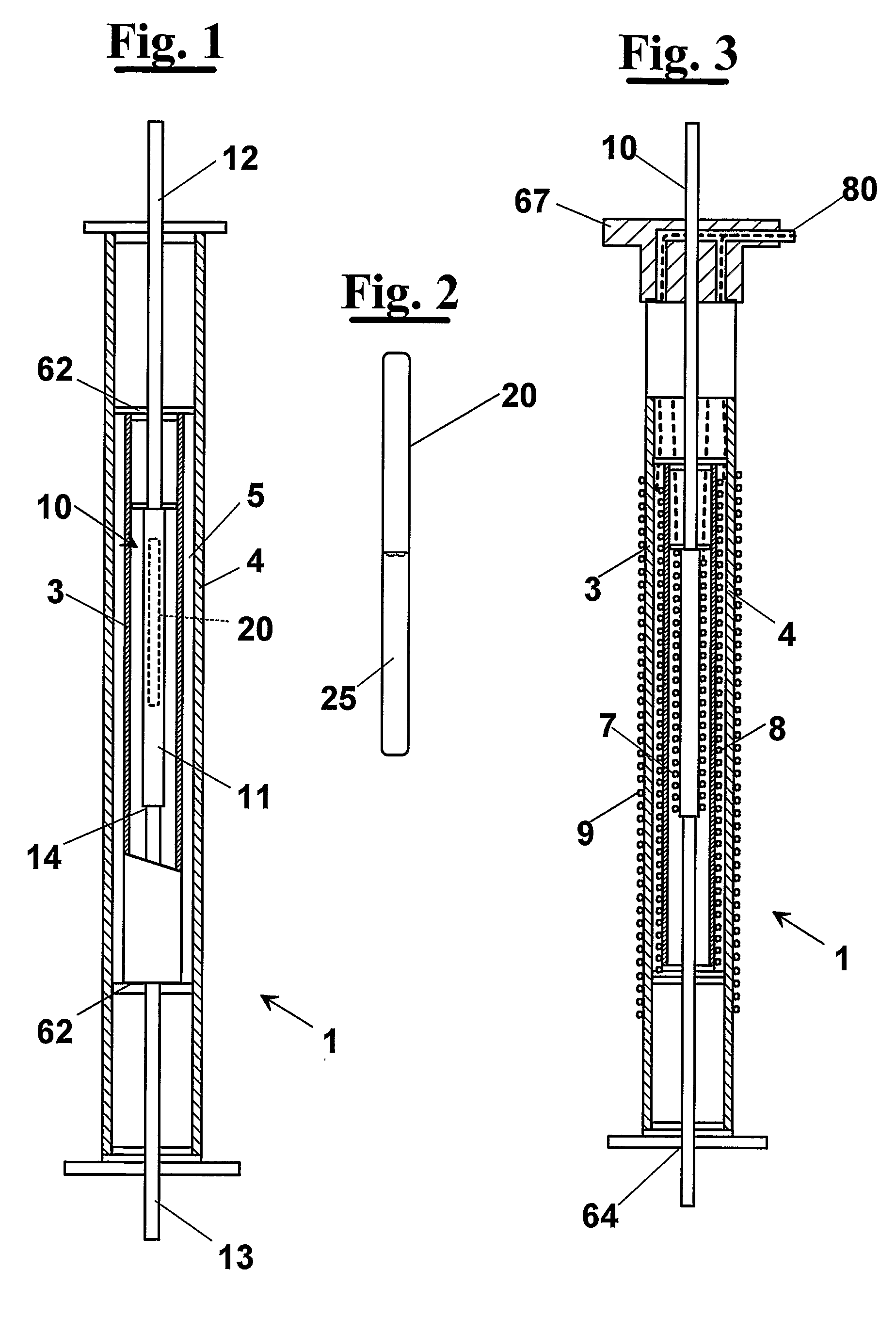
[0061]With reference to FIG. 1, a structure of calorimeter according to the invention provides a calorimetric head 1 comprising essentially a calorimetric cell 10 suitable for receiving a sample holding container 20, containing a sample 25 to examine. Cell 10 is arranged within a first shield 3, hereafter called active shield. Outside active shield 3 a second shield 4 is present, hereafter called dynamical shield, which comprises a cylindrical hollow body arranged around active shield 3 for all its length, in order to provide a space 5 of determined size.

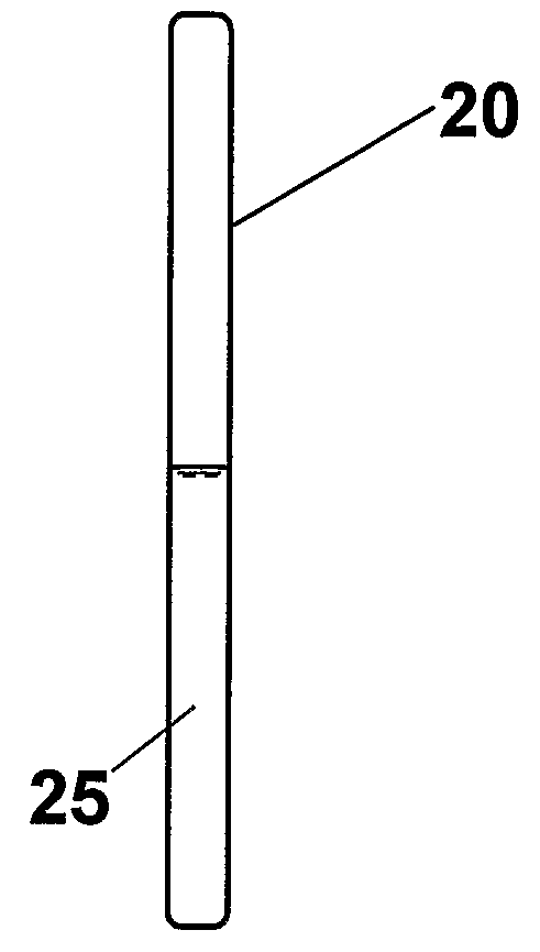
[0062]Sample holding container 20 can be a cylindrical tube, made for example of Pyrex glass or other material adapted to chemical and / or physical processes, shown in FIG. 2 in a way enlarged with respect to the cell of FIG. 1. Sample holding container 20 can be let down from the above into cell 10, for example by a wire.

[0063]An alternative configuration of the sample holding container is diagrammatically shown in FIG. 8 with 20′, ...


PUM


Abstract

A structure of calorimeter provides a calorimetric head (1) comprising a calorimetric cell (10) suitable for receiving a sample holding container (20) containing a sample (25) to examine. The cell (10) is arranged according to a first shield (3), or active shield. Outside the active shield (3) a second shield (4), or dynamical shield is present, which comprises a cylindrical hollow body arranged around the active shield (3) for all its length in order to provide a space (5) of determined size. Outside the active shield a thermal bath is present (not shown) at a temperature lower than the first and the second shield (3,4). The dynamic shield (4) allows an effective adjustment of the heat flux through the active shield (3) during calorimetric measures by limiting the heat flux same. In fact, in operative conditions the dynamic shield acts as thermal flywheel and keeps constant the heat flux coming from the active shield (3). More in detail, the presence of the dynamic shield (4) ensures the reduction of the temperature gradient on the active shield (3) and then on the cell (10) containing the sample (20). Furthermore, by keeping the dynamic shield (4) at a suitable temperature difference from the active shield (3), the temperature can be controlled with much less electric power than it would be necessary if the active shield (3) exchanged heat directly with the thermal bath.

Description


Claims


Application Information

Patent Timeline
Owner CONSIGLIO NAT DELLE RICERCHE
Why Eureka
Try Eureka