Eureka AIR delivers breakthrough ideas for toughest innovation challenges, trusted by R&D personnel around the world.

Power saw comprising a display device

Inactive Publication Date: 2009-02-24
ISELE SIEGFRIED +1
View PDF15 Cites 6 Cited by
  • Summary
  • Abstract
  • Description
  • Claims
  • Application Information

AI Technical Summary

Benefits of technology

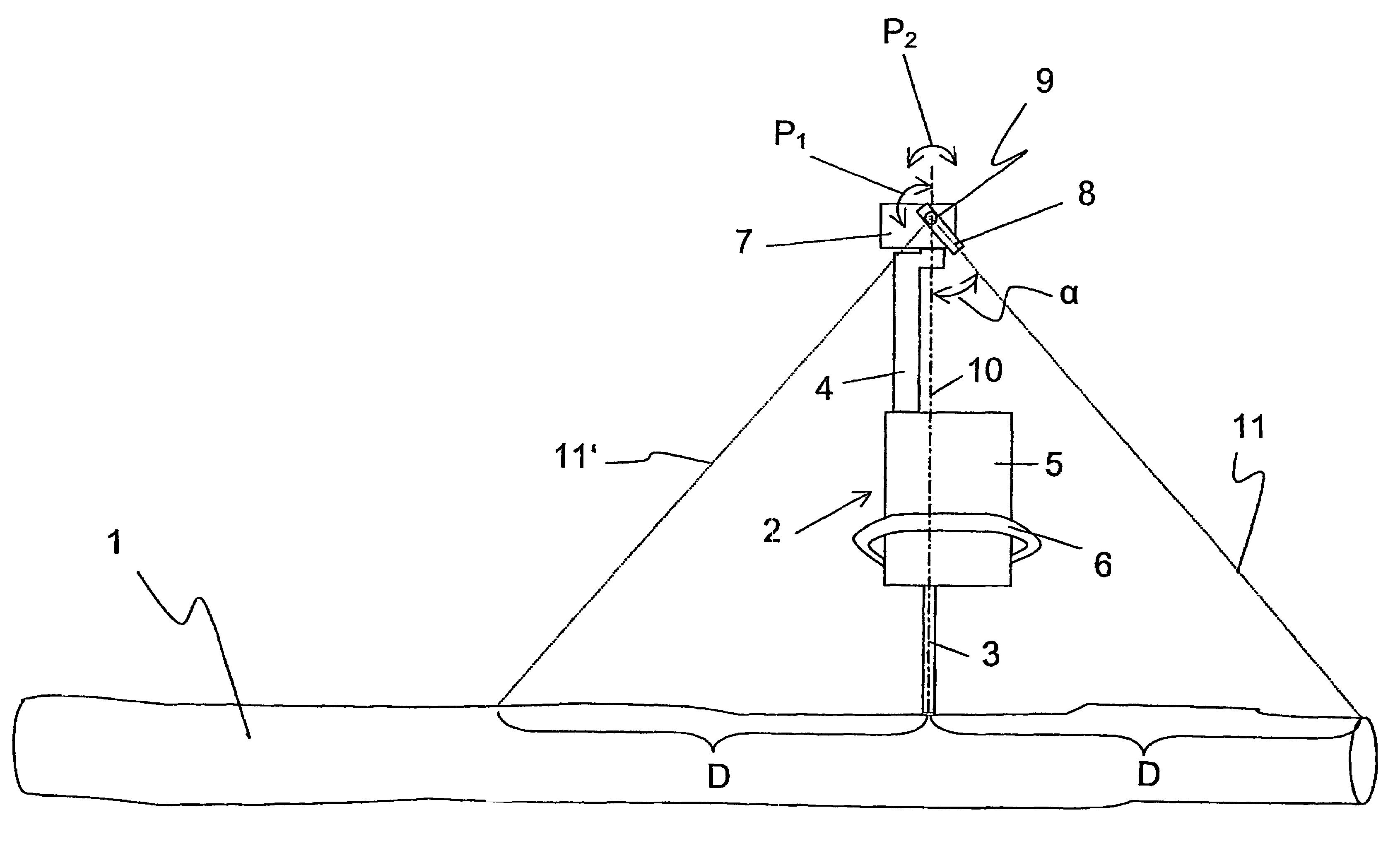
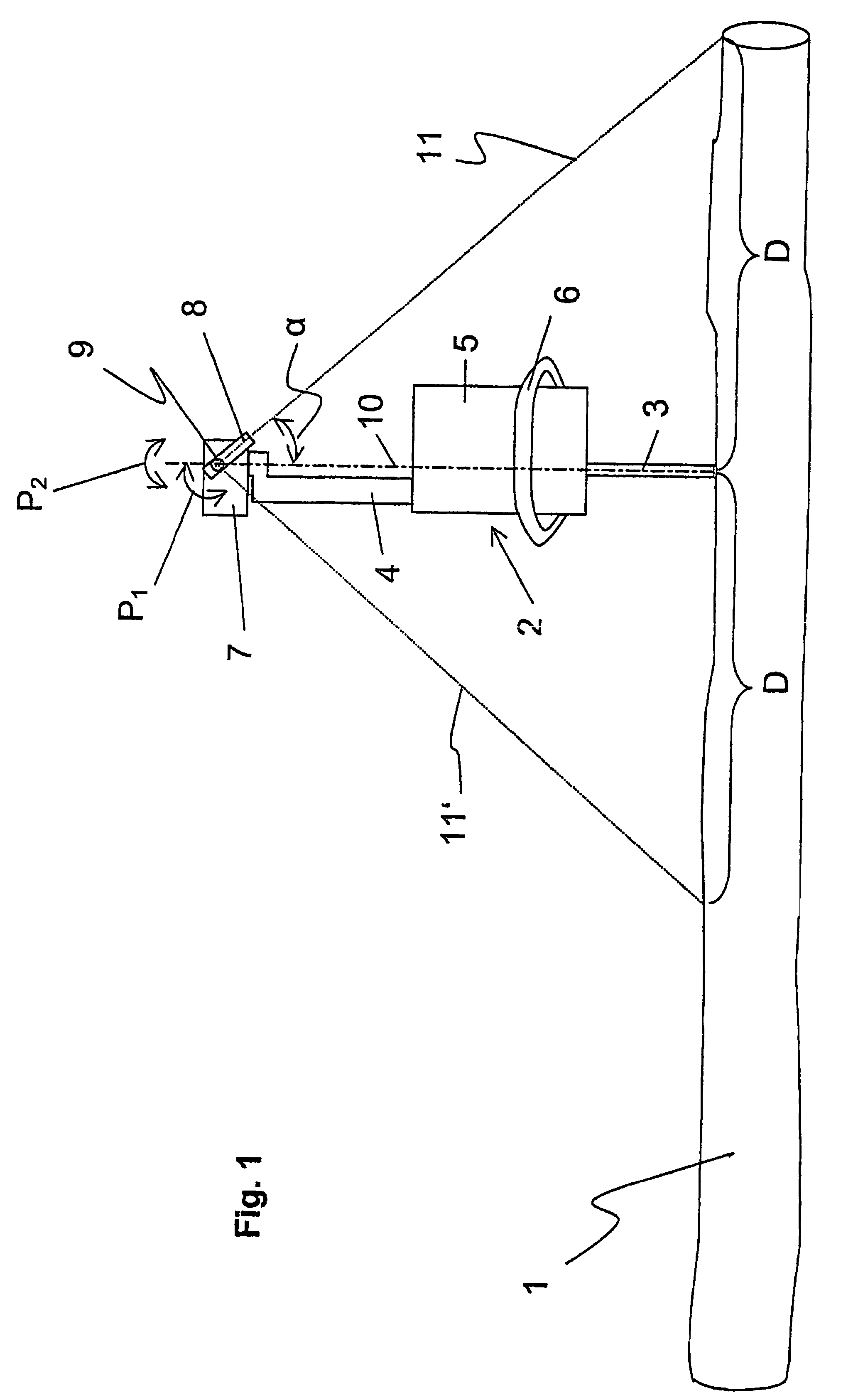
[0009]With a point or a line, the laser marks a certain distance between the tool and the striking area of the laser on the workpiece with a laser beam on the tool. A certain distance is determined by a determined angle of the laser or by the laser beam relative to the tool axis. As a result, for example, the crosscutting in a workpiece can be carried out very rapidly since the laser point or, if a line laser is used, the laser line has to be positioned only on the last work location or on a given location on the workpiece and the tool is consequently arranged at the predetermined interval. This makes it possible to divide, for example, tree trunks, into predetermined sections especially rapidly and in a simple manner. Furthermore, the laser line serves to precisely position the motor saw at a right angle and in the correct axis. If the saw is not properly aligned the line disappears from the tree trunk and therefore serves as a signal for a better aligning of the saw relative to the tree trunk.
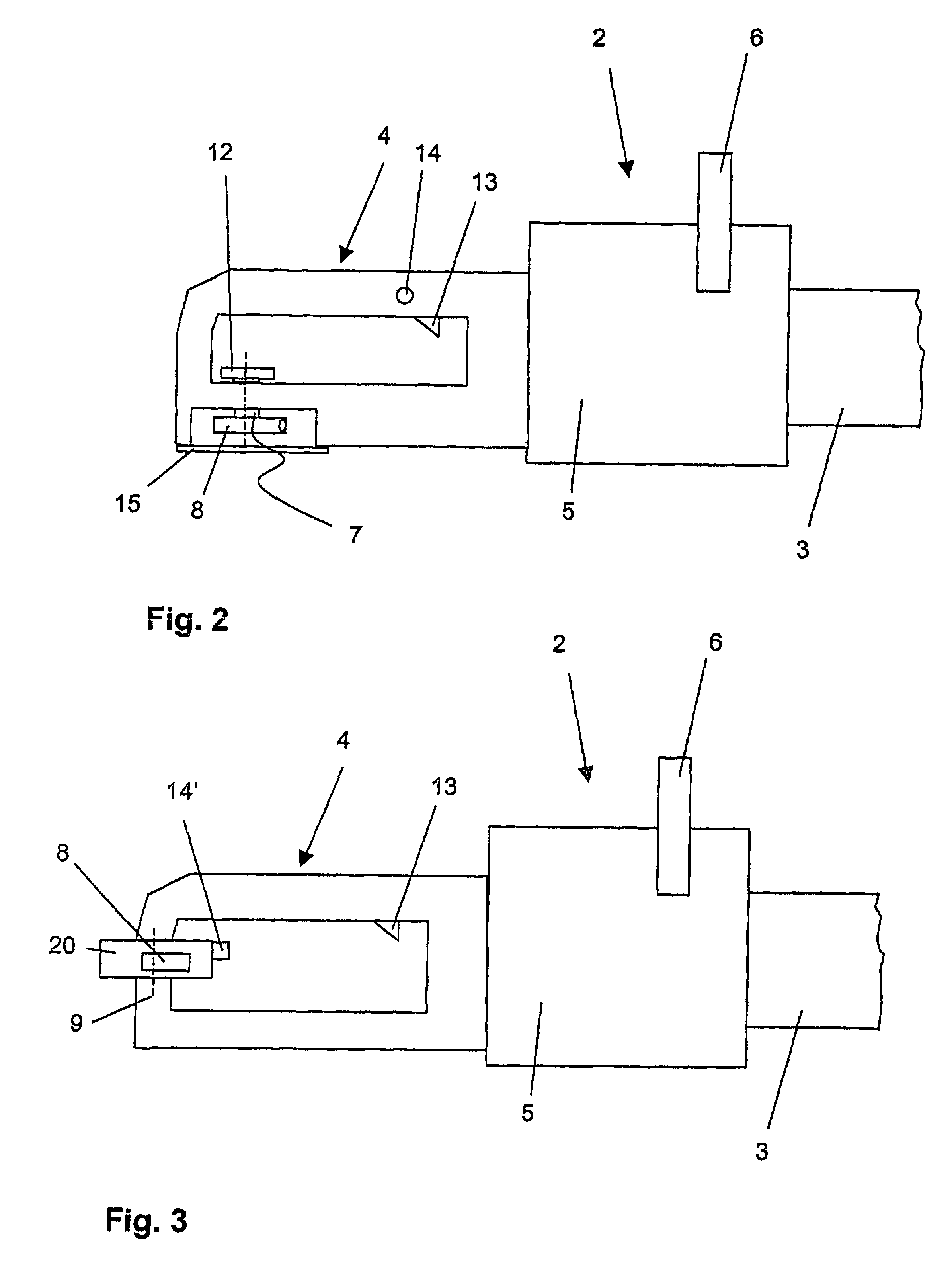
[0031]In an ergonomically especially advantageous embodiment of the invention, the switch is not arranged on the laser carrier but rather on the handle or holder. In this instance, the switch can be actuated as needed, e.g., by the thumb. If the laser is not needed, that is for example, after a marking was produced by the saw on the material to be cut, the laser can be turned off again or let go of if there is a touch-control switch. This saves current consumption and extends the service life of the laser.

Problems solved by technology

This is especially difficult when working on a slope.
This hand measuring device has the disadvantage that although a certain distance can be displayed as when using a cross-cut measuring rod, the starting and end points of the distance must be marked, e.g., with a pencil, on the workpiece to be measured.
In addition to other disadvantages, the described auxiliary means are not especially easy to use.
This requires a significant amount of time and is problematic for the workers.
Moreover, it is arranged on a very exposed position of the saw and is therefore not suitable for resisting the rough conditions in forestry work.

Method used


Image

  • Power saw comprising a display device
  • Power saw comprising a display device
  • Power saw comprising a display device

Examples


Embodiment Construction

[0038]Reference will now be made in detail to embodiments of the present invention, one or more examples of which are illustrated in the drawings. Each example is provided by way of explanation of the invention, and not meant as a limitation of the invention. For example, features illustrated or described as part of one embodiment can be used with another embodiment to yield still a third embodiment. It is intended that the present invention include these and other modifications and variations.

[0039]FIG. 1 shows a sketched tree trunk 1 and a motor saw 2. Motor saw 2 consists of saw blade 3, handle 4, and motor 5 arranged between them. Bracket 6 is arranged on motor 5 or its housing in order to be able to hold motor saw 2 better. Holder 7 is provided on handle 4 on the end of motor saw 2 facing away from saw blade 3.

[0040]A laser 8 is fastened on holder 7. Laser 8 is mounted so that it can rotate by means of swivel pin 9 in arrow direction P1 in order to be able to assume a predeterm...


PUM

PropertyMeasurementUnit
Fractionaaaaaaaaaa
Angleaaaaaaaaaa
Angleaaaaaaaaaa

Abstract

A cutting tool is provided having a marking feature to facilitate the cutting of materials at desired lengths. The tool includes a laser that provides a beam for marking the material at a determined length based on the angle that the beam forms with the cutting axis of the tool. The tool may be configured so that the beam can be emitted on either side of the tool. The tool may be reconfigured so that the angle of the beam relative to the cutting axis of the tool is selectively adjustable.

Description

TECHNICAL FIELD OF THE INVENTION[0001]The present invention relates to a cutting tool display device that provides a marking feature to facilitate the cutting of materials at desired lengths. The tool includes a laser that provides a beam for marking the material at a determined length based on the angle that the beam forms with the cutting axis of the tool.BACKGROUND OF THE INVENTION[0002]DE 199 04 679 A1 teaches a laser-adjusted measuring aid for workers in woods and forests. The measuring aid disclosed in it is intended to replace a cross-cut measuring rod, a measuring tape, or a slide caliper. To this end two laser pointers are arranged at an angle to one another in a holder. The laser beams form a type of distance compasses with which a defined length can be measured at a predetermined interval of the holder to the piece of wood to be measured. The holder is fastened to this end, e.g., on a belt, and adjusted or set to the particular height of the belt from the ground below. Tw...

Claims


Application Information

Patent Timeline
IPC IPC(8): G01C15/00B26D7/28B27B17/00B23D59/00B23Q17/24
CPCB23D59/002B23Q17/24B27B17/0025Y10S33/21Y10T83/853
Inventor ISELE, SIEGFRIEDBASLER, RALF
Owner ISELE SIEGFRIED
Why Eureka
Eureka Blog
Learn More