
Concentric expandable reamer and method

Inactive Publication Date: 2009-02-24
SMITH INT INC
View PDF22 Cites 69 Cited by
  • Summary
  • Abstract
  • Description
  • Claims
  • Application Information

AI Technical Summary

Benefits of technology

[0019]An expandable downhole tool is disclosed for use with a drilling assembly in a wellbore comprising a tubular body, at least one moveable arm disposed within the tubular body and being radially translatable between a retracted position and a wellbore engaging position, and at least one piston operable to mechanically support the at least one moveable arm in the wellbore engaging position when an opposing force is exerted. In an embodiment, the piston is axially translatable in response to a differential pressure between an axial flowbore within the tool and the wellbore. In an embodiment, the moveable arm includes at least one set of cutting structures for reaming the wellbore in the wellbore engaging position. The moveable arm may also comprise a back-reaming cutter. The expandable downhole tool may further comprise at least one gage pad for stabilizing the drilling assembly in the wellbore engaging position. The gage pad may be removable and replaceable. Cutters may also be provided adjacent the at least one gage pad. In an embodiment, the tool further comprises a sliding sleeve biased to isolate the at least one piston from the axial flowbore, thereby preventing the at least one moveable arm from translating between the retracted position and the wellbore engaging position. A droppable or pumpable actuator may be provided for aligning the sliding sleeve to expose the at least one piston to the axial flowbore. In an embodiment, the tool further comprises at least one nozzle disposed adjacent the at least one moveable arm.
[0020]Also disc

Problems solved by technology

As successively smaller diameter casing strings are suspended, the annular area between the casing and the borehole wall is increasingly limited for the cementing operation.
A number of disadvantages are associated with this design.
In particular, due to directional tendency problems, these eccentric reamer portions have difficulty reliably enlarging the borehole to the desired diameter.
With respect to a bi-center bit, the eccentric reaming section tends to cause the pilot bit to wobble and undesirably deviate off center, and any off-center rotation will cause the reaming section to drill an enlarged borehole that is undersized.
A similar problem is experienced with respect to winged reamers, which only enlarge the borehole to the desired diameter if the pilot bit remains centralized in the borehole during drilling.
Thus, although a fixed-blade reamer remains concentrically disposed as it rotates to enlarge the borehole, it is limited to enlarging the borehole only to the drift diameter of the existing cased borehole, whereas winged reamers and bi-center bits can enlarge the borehole beyond the drift diameter of the casing.
First, the pivoted arms may break during the drilling operation, requiring that the arms be removed or “fished” out of the borehole before the drilling operation can continue.
Accordingly, due to the limited strength of the pivoted arms, this type of reamer may be incapable of underreaming harder rock formations, or may have unacceptably slow rates of penetration.
Further, if the pivoted arms do not fully retract, the drill string may easily hang up when attempting to remove it from the borehole.
Accordingly, if too much weight is applied to the internal components, the reamer may not have enough hydraulic power to lift the weight below the reamer, and the reamer will not open.
Further, it may not be possible to set weight-on-bit when the reamer should be activated to extend the blades.
With such designs, there is no certainty that all of the blades will be fully extended because the blades do not activate in unison.
Further, most expandable tools include a large number of moving parts, thereby increasing the probability of malfunction.
There are also disadvantages associated with existing reamer blades.
Further, most blades fail to include pads on the gage configuration for stability and durability, or if pads are included, the blades fail to include active cutting structures near the pads.

Method used


Image

  • Concentric expandable reamer and method
  • Concentric expandable reamer and method
  • Concentric expandable reamer and method

Examples


Embodiment Construction

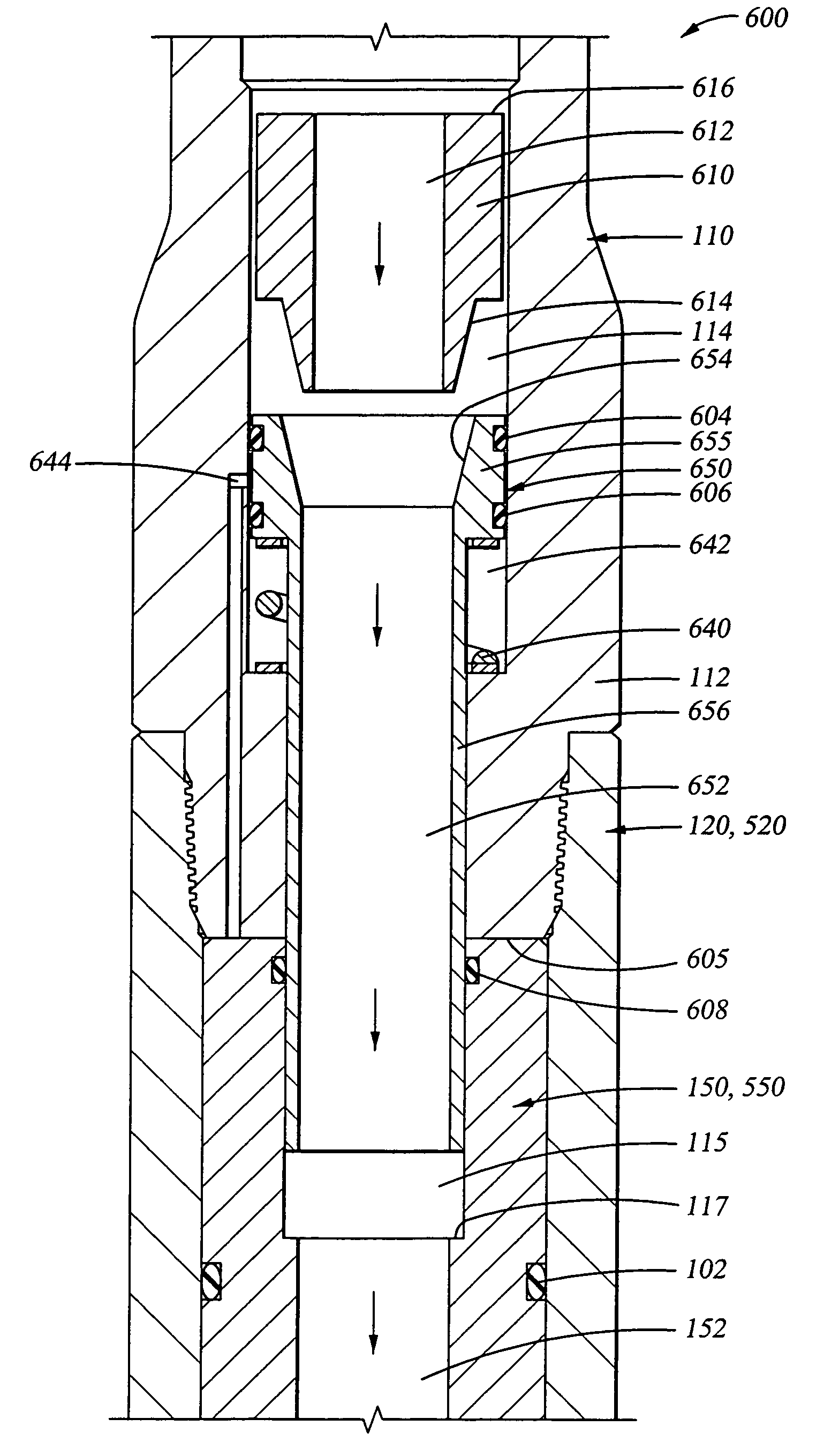
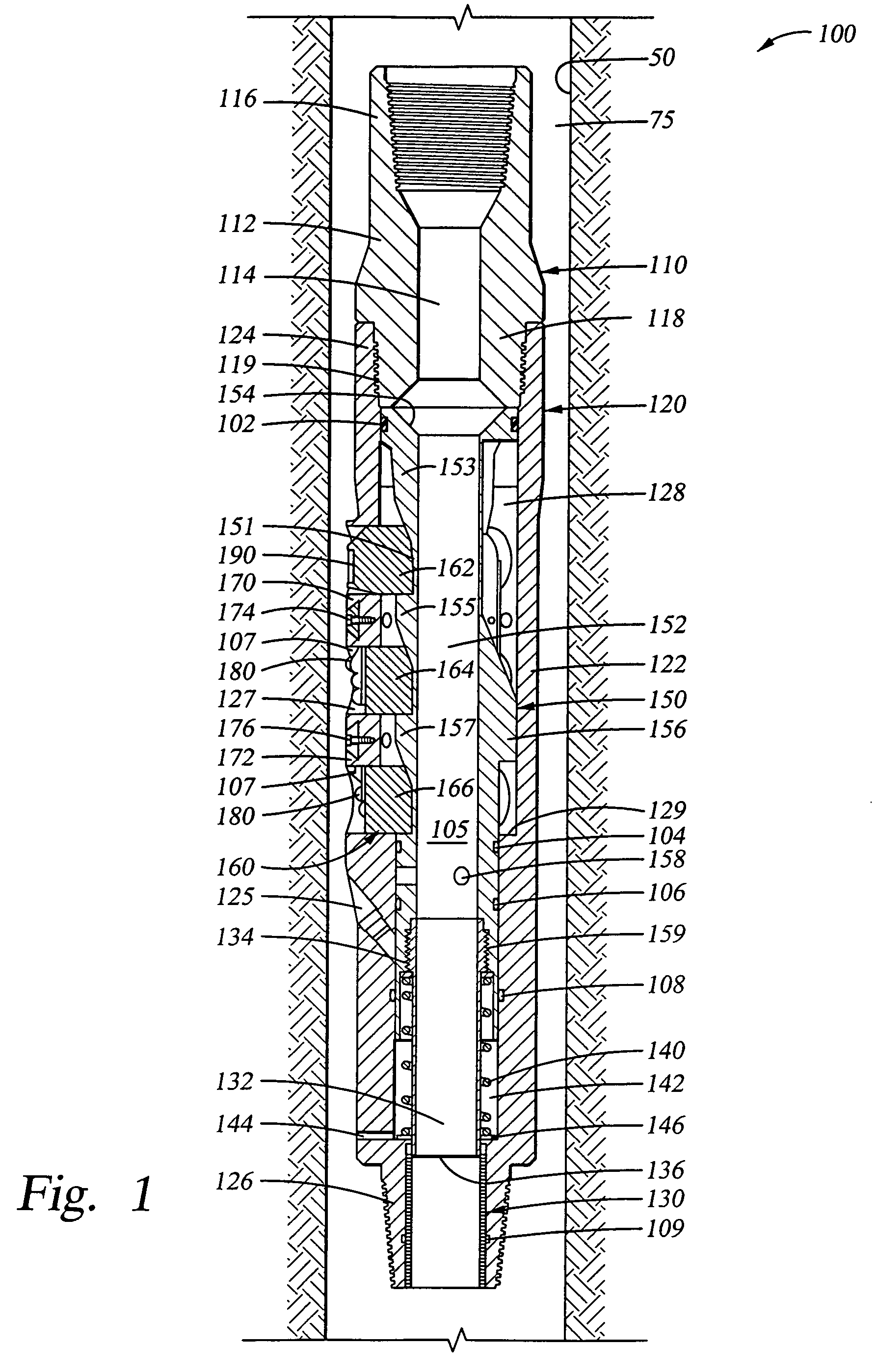
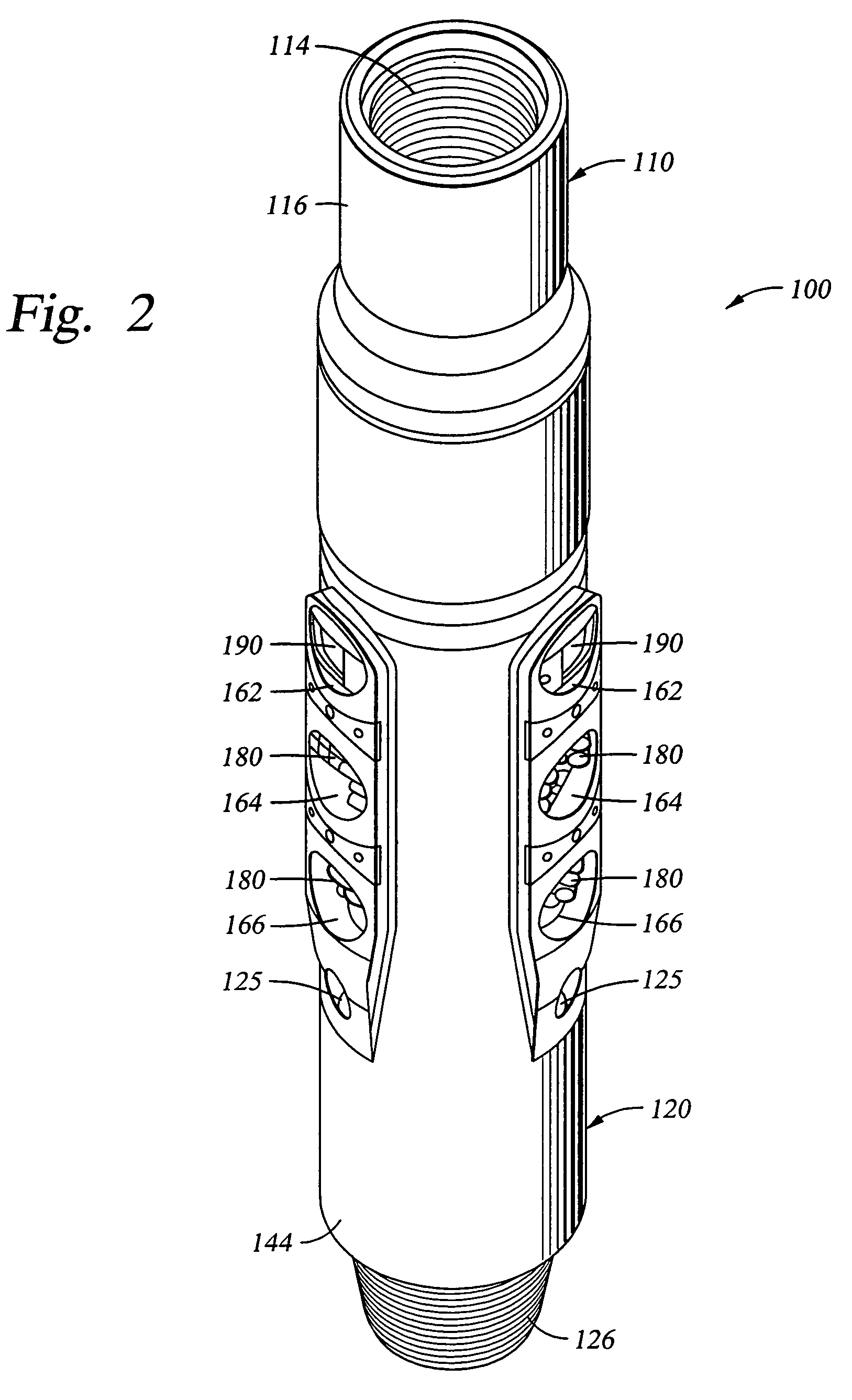
[0047]The concentric expandable tool is susceptible to embodiments of different forms. There are shown in the drawings, and herein will be described in detail, specific embodiments of the tool with the understanding that the disclosure is to be considered an exemplification of the principles of the tool, and is not intended to limit the tool to that illustrated and described herein.

[0048]In particular, various embodiments of the concentric expandable tool provide a number of different constructions and methods of operation. Each of the various embodiments may be used to enlarge a borehole, or to perform another downhole function with an expandable tool, such as stabilization, for example. Thus, the concentric expandable tool may be utilized as a reamer, a stabilizer, or as any other type of expandable tool. The various embodiments of the tool also provide a plurality of methods for use in a drilling assembly. It is to be fully recognized that the different teachings of the embodimen...


PUM


Abstract

An expandable downhole tool comprises a tubular body, at least one moveable arm disposed within the tubular body and being radially translatable between a retracted position and a wellbore engaging position, and at least one piston operable to mechanically support the at least one moveable arm in the wellbore engaging position when an opposing force is exerted. A method of reaming a formation to form an enlarged borehole in a wellbore comprising disposing an expandable reamer in a retracted position in the wellbore, expanding at least one movable arm of the expandable reamer radially outwardly into engagement with the formation, reaming the formation with the at least one moveable arm to form the enlarged borehole; and mechanically supporting the at least one moveable arm in the radially outward direction during reaming.

Description

CROSS-REFERENCE TO RELATED APPLICATIONS[0001]The present application claims the benefit under 35 U.S.C. § 119 of U.S. provisional application Ser. No. 60 / 468,767 filed May 8, 2003 and entitled “Concentric Expandable Reamer”, hereby incorporated herein by reference for all purposes.STATEMENT REGARDING FEDERALLY SPONSORED RESEARCH OR DEVELOPMENT[0002]Not Applicable.BACKGROUND OF THE INVENTION[0003]1. Field of the Invention[0004]The present invention relates generally to expandable downhole tools. More particularly, the present invention relates to a concentric expandable downhole tool having fewer components and thus a shorter length than conventional expandable tools. Still more particularly, the present invention relates to a robust, concentric expandable reamer having an advanced cutting structure and a mechanical / hydraulic activation mechanism.[0005]2. Description of the Related Art[0006]In the drilling of oil and gas wells, a plurality of casing strings are installed concentrical...

Claims


Application Information

Patent Timeline
IPC IPC(8): E21B10/62E21B10/32
CPCE21B10/322
Inventor NEVLUD, KENNETH M.BEATON, TIMOTHY P.
Owner SMITH INT INC
Features
  • Generate Ideas
  • Intellectual Property
  • Life Sciences
  • Materials
  • Tech Scout
  • Unparalleled Data Quality
  • Higher Quality Content
  • 60% Fewer Hallucinations
Learn More