
Variable spaced conveyor belt

a conveyor belt and variable space technology, applied in the field of conveyor belts, can solve the problems of reducing the overall cost of manufacturing the conveyor belt, and reducing the overall cost of manufacturing the belt, so as to achieve the effect of withstanding the tension applied and without fatigu

Active Publication Date: 2009-02-24
CAMBRIDGE INT
View PDF40 Cites 24 Cited by
  • Summary
  • Abstract
  • Description
  • Claims
  • Application Information

AI Technical Summary

Benefits of technology

"The patent describes a conveyor belt that has a variable spacing between the rods and wickets. The wickets are made up of two rows, with the first rows having a smaller spacing between them than the second rows. This design makes the edges of the conveyor belt stronger and more durable, allowing it to withstand tension without getting fatigue."

Problems solved by technology

Thus, it is believed that such flexing causes wicket breakage.
The use of reinforcing bars 14 on the outer edge of the conveyor belt is not entirely successful in eliminating fatigue failures on the outer edge 12.
While the conveyor belt of the '448 patent exhibits outstanding performance and has enjoyed substantial commercial success, the use of heavier gauge material for the tension links substantially increases the overall costs of manufacturing the belt.

Method used


Image

  • Variable spaced conveyor belt
  • Variable spaced conveyor belt
  • Variable spaced conveyor belt

Examples


Embodiment Construction

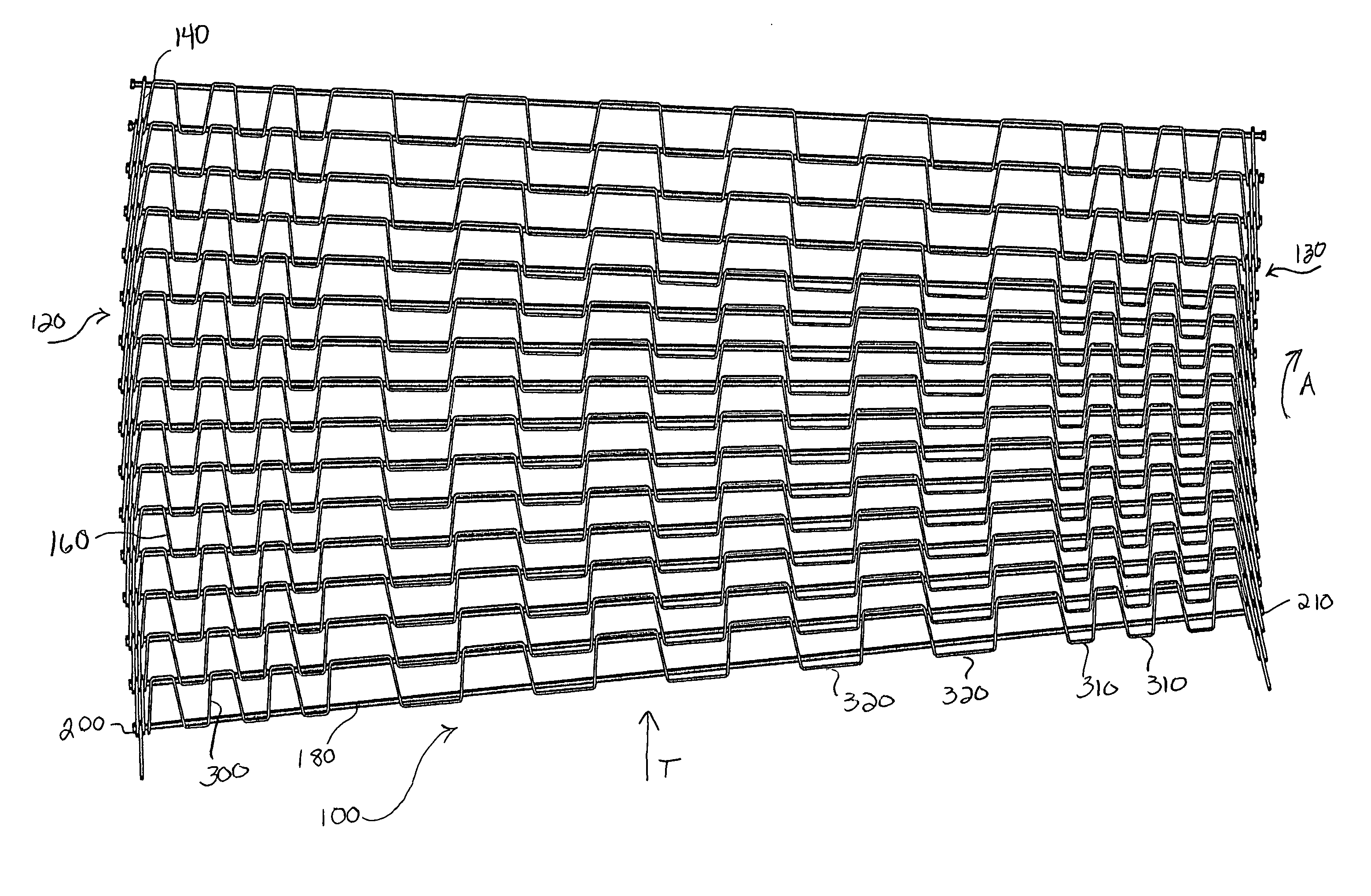
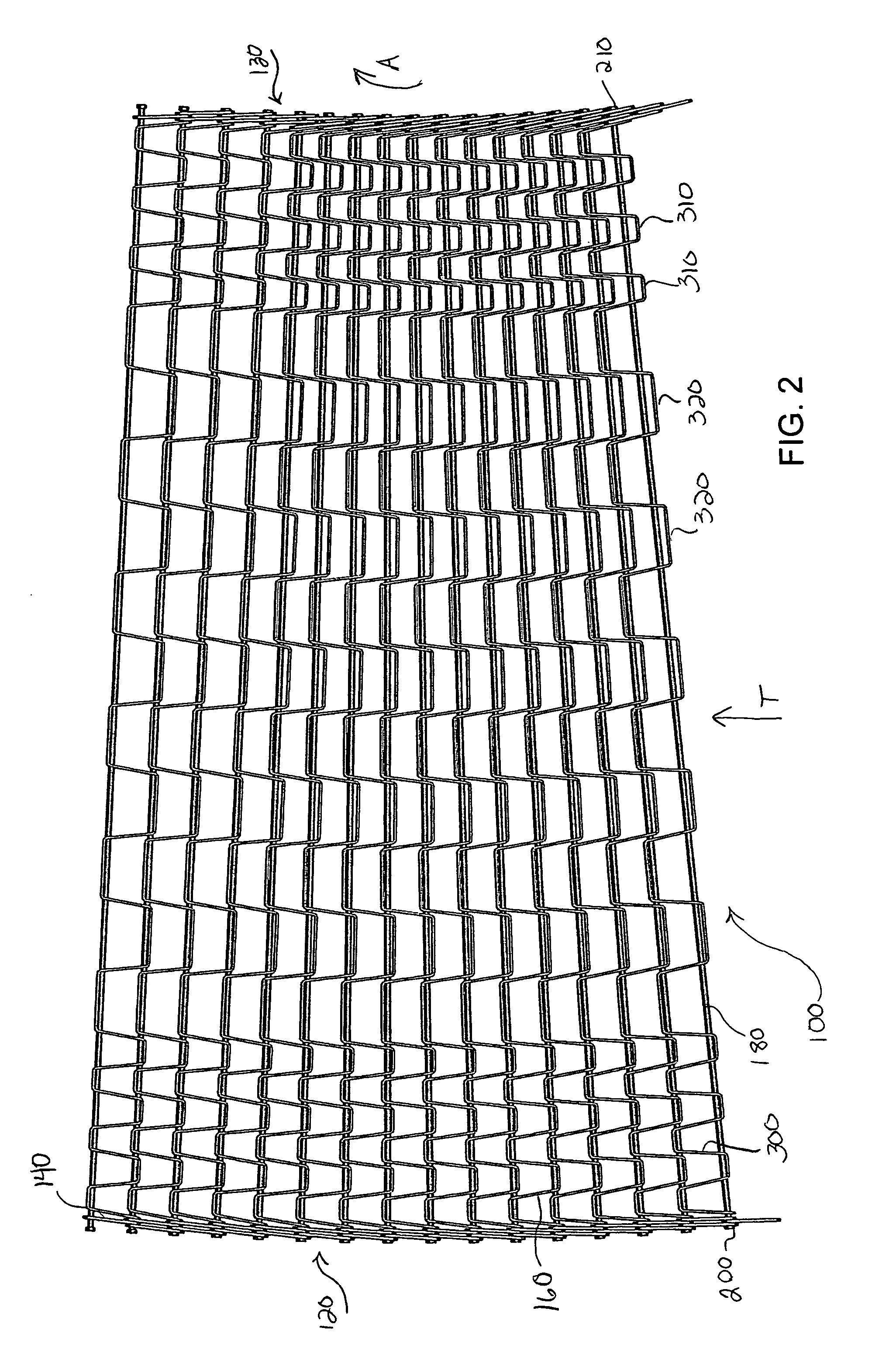
[0016]A conveyor belt in accordance with the present invention is shown generally in FIG. 2 by reference numeral 100. Conveyor belt 100 preferably comprises a flat wire conveyor belt including a plurality of spaced tractive rods 180 disposed in succession and transversely with respect to a direction of travel T as represented by arrow T of belt 100, each rod 180 having two ends 200 and 210.

[0017]Belt 100 has a transport course preferably including at least one course turn deviating in a direction selected from the group consisting of a left course turn and a right course turn. When belt 100 is in a right course turn as represented by arrow A, belt 100 has an outside edge 120 and an inside edge 130. Belt 100 also has a straight transport course, also exemplified by arrow T, which is generally downstream of a left or right course turn of belt 100.

[0018]Belt 100 includes a plurality of rows of wickets 160 transversely disposed with respect to the direction of travel T, and interconnect...


PUM


Abstract

A variable spaced conveyor belt includes a plurality of spaced tractive rods and a plurality of rows of wickets transversely disposed with respect to a direction of travel and interconnecting the plurality of spaced tractive rods, each of the rows of wickets including a plurality of first links and a plurality of second links, the plurality of first links have a first spacing and the plurality of second links have a second spacing, the first spacing being less than the second spacing.

Description

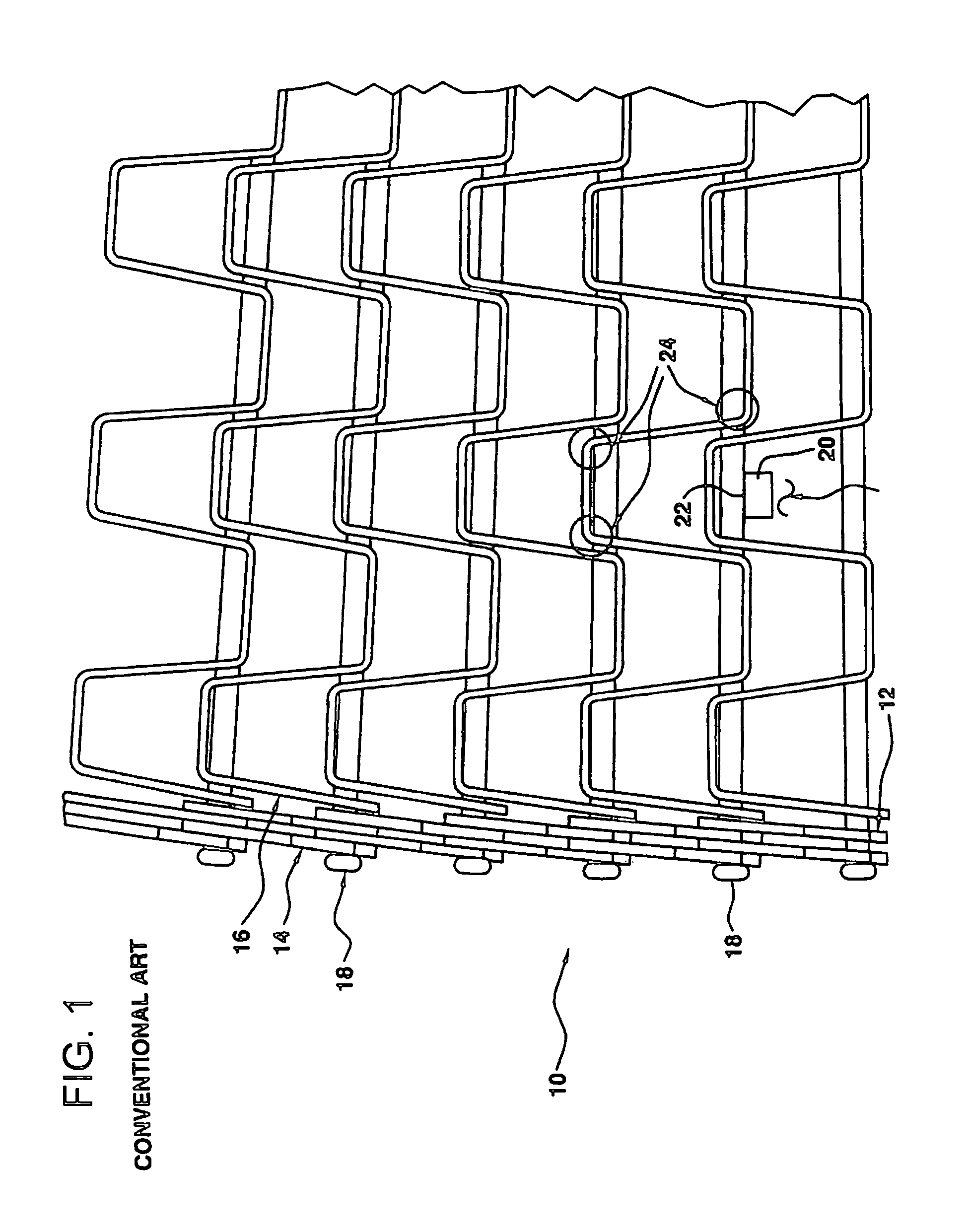
FIELD OF THE INVENTION[0001]The present invention is directed to a conveyor belt, more particularly to a conveyor belt having a variable spaced wire links, and still more particularly, to a flat wire conveyor belt having variable spaced wire links.BACKGROUND OF THE INVENTION[0002]With reference to FIG. 1, when a flat wire conveyor belt 10 is used in a spiral system or turn, tension is carried on the outer edge 12 of belt 10 by reinforcing bars 14. The wickets 16 on belt 10 are for product support, rather than taking a load, and the rods 18 are utilized to hold the components of belt 10 together, and to transmit drive forces to the outside edge 12 of belt 10.[0003]In a straight run, such as the infeed and discharge areas of a spiral system, the outer reinforcing bars 14 have little if any effect on the function of belt 10. A sprocket 20 tooth, which engages rods in a straight transport course downstream of a course turn, causes rod 18 to deflect at sprocket 20, releasing tension from...

Claims


Application Information

Patent Timeline
Patent Type & Authority Patents(United States)
IPC IPC(8): B65G15/54
CPCB65G17/064B65G17/086
Inventor MESSICK, JR., GEORGE H.MAINE, JR., ROBERT E.
Owner CAMBRIDGE INT
Learn More