Small feature point visual tracking and real-time quality test device for sheet steel weld joints

A technology for visual inspection and real-time quality, applied in measuring devices, auxiliary devices, optical devices, etc., can solve the problems of high installation accuracy of binocular vision system, inability to complete real-time welding real-time inspection, and unsuitable for complex weld shapes. , to achieve the effect of improving welding accuracy and efficiency, saving welding time and improving welding quality

Active Publication Date: 2014-11-19
HEBEI UNIV OF TECH
View PDF8 Cites 7 Cited by
  • Summary
  • Abstract
  • Description
  • Claims
  • Application Information

AI Technical Summary

Problems solved by technology

[0003] CN102794566A discloses "on-line monitoring device for laser welding quality based on paraxial CCD". The visual sensor in the device can not only detect the position of welding feature points, but also realize the detection of welding quality, but the equipment cannot complete the integration of real-time welding and real-time detection
[0004] CN101750416A discloses "a visual weld surface quality detection sensor based on line structured light". Two sensing units are respectively placed on both sides of the upper and lower surfaces of the weld, and the images of the upper and lower surfaces are respectively collected for quality inspection. This device It is used for post-weld inspection, and cannot complete instant welding instant inspection
[0005] CN102478390A reported "Surface Shape Acquisition and Sensing System of Welding Pool Based on Binocular Vision". Through binocular vision, the images on both sides of the molten pool are collected respectively and detected to obtain the shape information of the molten pool. However, the installation accuracy of the binocular vision system High requirements, not suitable for detection of complex weld shapes

Method used


Image

  • Small feature point visual tracking and real-time quality test device for sheet steel weld joints
  • Small feature point visual tracking and real-time quality test device for sheet steel weld joints
  • Small feature point visual tracking and real-time quality test device for sheet steel weld joints

Examples


Embodiment Construction

[0025] The embodiments of the present invention will be described in detail below, but the scope of the present invention cannot be limited thereto. Any replacement, combination, and separation of components known in the technical field to the mechanism of the present invention, as well as equivalent changes or replacements to the implementation steps of the present invention that are well known in the technical field are within the disclosure and protection scope of the present invention.

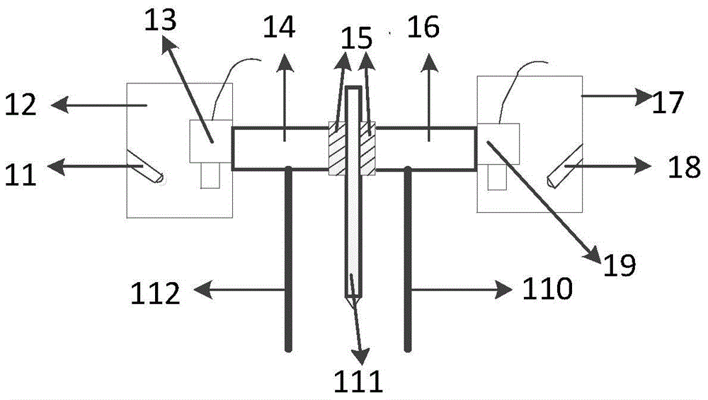
[0026] A visual tracking and real-time quality inspection device for small feature points of thin steel plate welds, the device includes a main control computer, PLC, motor and sensing parts;

[0027] Described sensing part mainly comprises welding torch 111, and the feature point visual detection sensor 17 of welding torch 111 left and right sides and visual quality detection sensor 12, and wherein welding torch 111 both sides are each rigidly connected with a connecting block 15; A connec...


PUM


Abstract

The invention relates to a small feature point visual tracking and real-time quality test device for sheet steel weld joints. The device comprises a main control computer, a PLC, a motor and a sensing part; a feature point visual test sensor and a visual quality test sensor are both connected to the main control computer through USBs, the main control computer is connected with the PLC through a connecting line, the PLC is connected with the motor for controlling a welding gun to move through a connecting line, and the motor is in rigid connection with the welding gun. By means of the small feature point visual tracking and real-time quality test device, manpower can be replaced for doing welding quality test work and postwelding quality test work; on a production line, traditional welding depends on the eyes of a worker for weld joint testing and locating and conducting welding, but due to influences of factors such as fatigues, deviations are easily caused by eye testing. The intelligent test device for the weld joints can continuously run for a long time without the fatigues, and the welding accuracy and the welding efficiency are improved.

Description

technical field [0001] The technical solution of the present invention relates to the field of visual welding, specifically, the camera is used to replace the human eye to provide welding position parameters during the welding process and control the welding torch to perform real-time deviation correction to complete the welding, and to perform real-time online quality inspection of the welding after the welding is completed installation. Background technique [0002] As welding production efficiency and production quality become increasingly demanding, it is an extremely important application to introduce intelligent vision welding into the welding field. Vision sensors can replace human eyes in welding to identify and determine the position information of welding feature points to guide the welding torch Welding, at the same time, post-welding quality inspection can also be completed by visual sensors, traditionally rely on workers to rely on eyes for inspection, and manua...

Claims


Application Information

Patent Timeline
Patent Type & Authority Applications(China)
IPC IPC(8): B23K37/00G01N21/88G01B11/00
CPCB23K31/125B23K37/00G01B11/00
Inventor 陈海永杜晓琳孙鹤旭
Owner HEBEI UNIV OF TECH
Why Eureka
Try Eureka