Hook-on type rail

a technology of hook-on rails and rails, which is applied in the direction of mounting cabinets, curtain suspension devices, lighting support devices, etc., can solve the problems of metal racks that metal racks cannot be disassembled to occupy a large room, and the rear end of the rails cannot be easily moved, etc., and achieve the effect of stable hooking

Inactive Publication Date: 2009-02-24
PROTREND ENTERPRISE CO LTD
View PDF20 Cites 27 Cited by
  • Summary
  • Abstract
  • Description
  • Claims
  • Application Information

AI Technical Summary

Benefits of technology

[0005]A primary object of the present invention is to provide a hook-on type rail that could be stably hooked on posts provided with insertion holes without the risk of separating from the posts.
[0006]Another object of the present invention is to provide a hook-on type rail that includes front and rear hooking members adjustably connected to front and rear ends thereof, so that errors in the size of posts, to which the rail is mounted, could be compensated for the rail to always locate at a horizontal position.
[0007]To achieve the above and other objects, the hook-on type rail of the present invention includes a main body, a front hooking member adjustably connected to a rear outer end of the main body, and a second hooking member adjustably connected to a front outer end of the main body. The first hooking member has two sideward projected L-shaped hooks for firmly located in two insertion holes on a rear post of a sectional rack. The second hooking member includes two sideward projected lugs for fitly inserting into two insertion holes on a front post of the sectional rack to prevent the rail from moving up or down, and two vertically movable hooks bearing against one side of the two lugs for extending into and hooking on the same insertion holes to firmly hold the rail to the front post. Therefore, the rail may be stably hooked on the posts of the sectional rack for a drawer or the like to safely slide thereon.
[0008]The lugs on the second hooking member have a height similar to that of the insertion holes on the front post, enabling the lugs inserted into the insertion holes to prevent the rail from moving up or down.

Problems solved by technology

As a result, the metal rack could not be disassembled to occupy a big room, and is not easily movable.
However, when the drawer is pulled outward, there is a relatively large load on a front section of the rail and a relatively small load on a rear section of the rail, resulting in a lifted rear end of the rail and accordingly, a rail deviated from a desired horizontal position.
However, since there is always a considerably large gap left between an upper end of the hooks on the rail and an upper edge of the insertion holes, the rail tends to move upward and downward relative to the posts, and is therefore not ideal for use.

Method used


Image

  • Hook-on type rail
  • Hook-on type rail
  • Hook-on type rail

Examples


Embodiment Construction

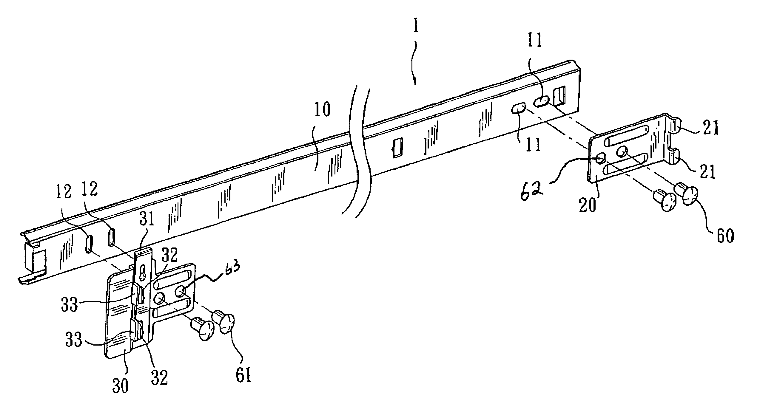
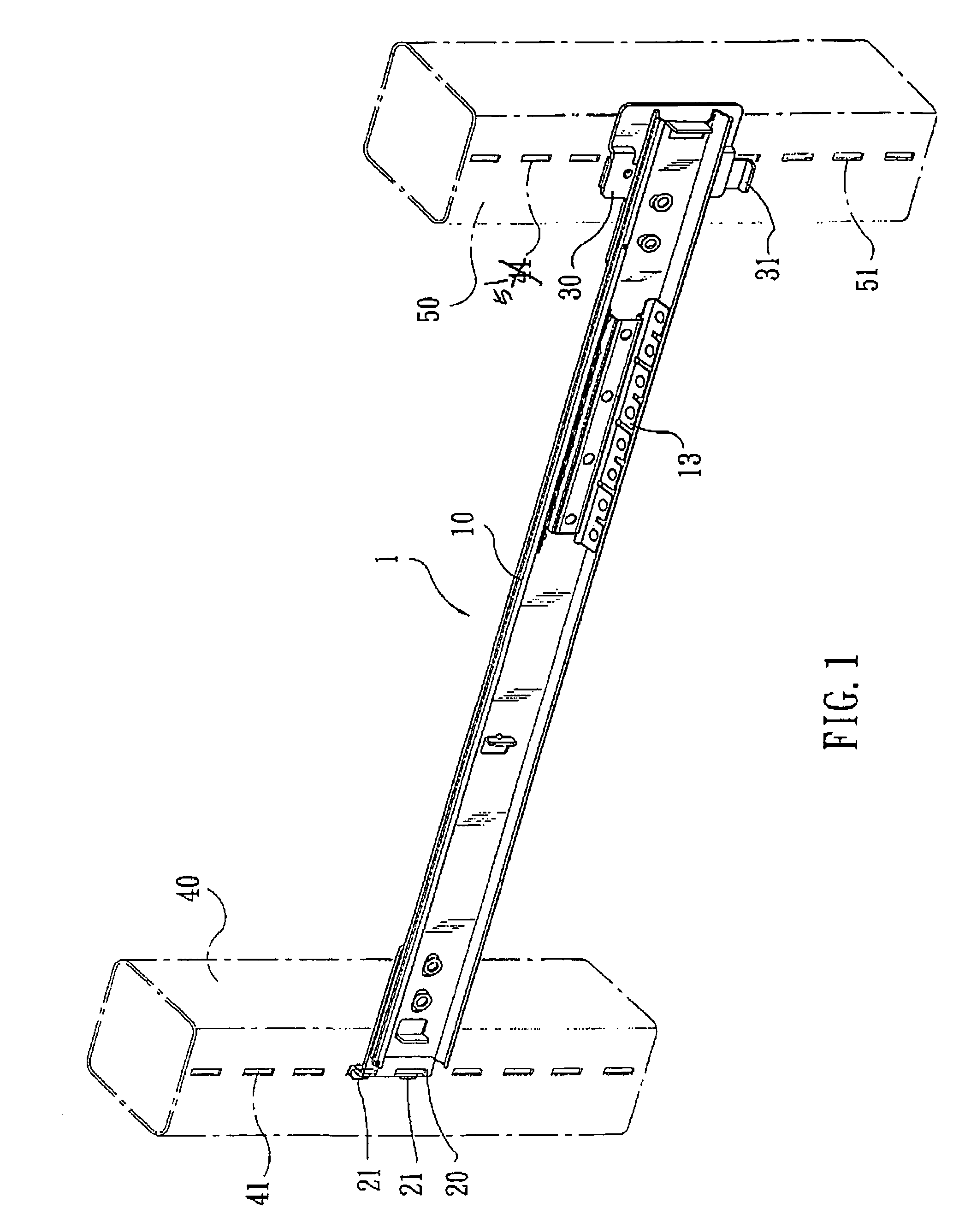
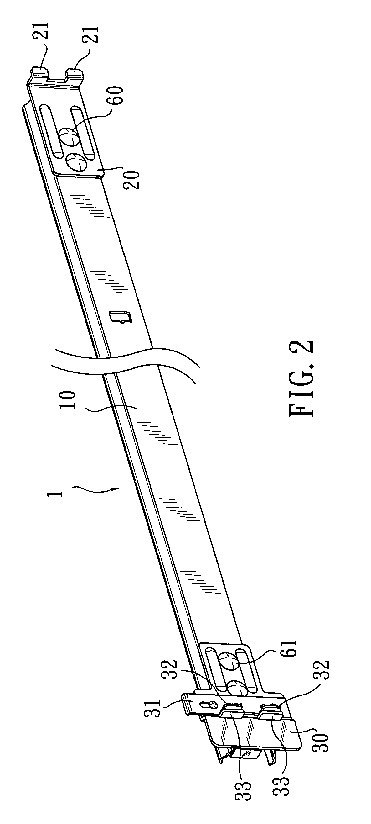
[0015]Please refer to FIGS. 1 to 3, in which a hook-on type rail 1 according to an embodiment of the present invention is shown. As shown, the rail 1 includes a main body 10, a first hooking member 20 adjustably attached to a rear outer end of the main body 10, and a second hooking member 30 adjustably attached to a front outer end of the main body 10.

[0016]The first hooking member 20 has a rear end formed into two vertically spaced and horizontally extended L-shaped hooks 21. The first hooking member 20 is mounted on the rail 1 with the two hooks 21 projected from the rear end of the main body 10.

[0017]The second hooking member 30 has a slide plate 31 vertically movably associated therewith. The slide plate 31 is formed at a front edge with two vertically spaced and downward extended hooks 32.

[0018]The rail 1 may be detachably connected at the rear end to a rear vertical post 40 of a sectional rack by inserting the two L-shaped hooks 21 of the first hooking member 20 into two verti...


PUM


Abstract

A hook-on type rail includes a main body, a front hooking member adjustably connected to a rear end of the main body, and a second hooking member adjustably connected to a front end of the main body. The first hooking member has two sideward projected hooks for firmly located in two insertion holes on a rear post of a sectional rack. The second hooking member includes two sideward projected lugs for fitly inserting into two insertion holes on a front post of the sectional rack to prevent the rail from moving up or down, and two vertically movable hooks bearing against one side of the two lugs for extending into and hooking on the same insertion holes to firmly hold the rail to the front post. Therefore, the rail may be stably hooked on the posts of the sectional rack for a drawer or the like to safely slide thereon.

Description

FIELD OF THE INVENTION[0001]The present invention relates to a hook-on type rail, and more particularly to a rail that could be conveniently and stably hooked on vertical posts of a sectional rack for a drawer or the like to safely slide thereon.BACKGROUND OF THE INVENTION[0002]A metal rack would be more useful when it is provided with one or more drawers or slidable baskets in addition to the normally included horizontal shelves. In the early stage, rails are directly welded to the posts of the metal rack. As a result, the metal rack could not be disassembled to occupy a big room, and is not easily movable.[0003]Currently, there are various types of sectional racks available in the market. Most of these sectional racks include vertical posts and horizontal shelves. Among others, there is a sectional rack using cone-shaped sleeves to connect the shelves to the vertical posts. When it is desired to mount a rail on the sectional rack, first weld two cone-shaped sleeves front and rear ...

Claims


Application Information

Patent Timeline
Patent Type & Authority Patents(United States)
IPC IPC(8): A47F5/00A47H1/10
CPCA47B88/044A47B88/43
Inventor CHEN, HENRY
Owner PROTREND ENTERPRISE CO LTD
Why Eureka
Try Eureka