Terminal fitting having bi-metallic caulking pieces

a technology of bi-metallic caulking and fittings, applied in the direction of coupling contact members, coupling device connections, connections effected by permanent deformation, etc., can solve the problems of imperfect contact, increased contact resistance value at the crimped part, etc., to improve contact pressure, improve contact pressure, and high contact pressure

Active Publication Date: 2009-02-24
YAZAKI CORP
View PDF5 Cites 46 Cited by
  • Summary
  • Abstract
  • Description
  • Claims
  • Application Information

AI Technical Summary

Benefits of technology

[0013]Thus, in the light of the above-mentioned problem, it is an object of the invention to provide a terminal fitting that can securely mount the core wires made of aluminum or aluminum alloy for the electric wire by suppressing the contact resistance at the crimped part and its mounting method.
[0018]With the first aspect of the invention, the aluminum terminal made of aluminum or aluminum alloy can be crimped from outside the terminal fitting main body made of copper or copper alloy, and the spring back of the terminal fitting main body made of copper or copper alloy can be suppressed by the aluminum terminal to improve a contact pressure between the aluminum terminal, the terminal fitting main body and the core wires. Since the core wires made of aluminum or aluminum alloy and the aluminum terminal have the roughly same spring back property, it is possible to attain the high contact pressure at the part where the aluminum terminal and the core wires are directly crimped.
[0026]With the third aspect of the invention, the aluminum terminal made of aluminum or aluminum alloy can be crimped from outside the terminal fitting main body made of copper or copper alloy, and the spring back of the terminal fitting main body made of copper or copper alloy can be suppressed by the aluminum terminal, thereby improving a contact pressure between the aluminum terminal, the terminal fitting main body and the core wires. Since the core wires made of aluminum or aluminum alloy and the aluminum terminal have the roughly same spring back property, it is possible to attain the high contact pressure at the part where the aluminum terminal and the core wires are directly crimped.
[0027]As described above, with the invention, the aluminum terminal made of aluminum or aluminum alloy can be crimped from outside the terminal fitting main body made of copper or copper alloy, and the spring back of the terminal fitting main body made of copper or copper alloy can be suppressed by the aluminum terminal, thereby improving a contact pressure between the aluminum terminal, the terminal fitting main body and the core wires. Since the core wires made of aluminum or aluminum alloy and the aluminum terminal have the roughly same spring back property, it is possible to attain the high contact pressure at the part where the aluminum terminal and the core wires are directly crimped. Therefore, the core wires made of aluminum or aluminum alloy for the electric wire can be securely mounted by suppressing the contact resistance at the crimped part.
[0028]With the second aspect of the invention, the ends of the first caulking pieces away from the first bottom wall provided in the aluminum terminal can bite into the aluminum core wire, forming an interference fit structure. Therefore, the core wires made of aluminum or aluminum alloy for the electric wire can be securely mounted by suppressing the contact resistance at the crimped part.
[0029]With the third aspect of the invention, the spring back of the terminal fitting main body made of copper or copper alloy is securely suppressed, and the contact are a between the aluminum terminal and the terminal fitting main body and the terminal fitting main body and the core wires can be increased. Therefore, the core wires made of aluminum or aluminum alloy for the electric wire can be securely mounted by suppressing the contact resistance at the crimped part.

Problems solved by technology

Therefore, if the terminal fitting 20 made of copper or copper alloy is caulked to crimp the core wires 11 made of aluminum or aluminum alloy, the core wires are placed in a loose crimped state, whereby there was a problem that the contact resistance value at the crimped part increased to cause an imperfect contact.

Method used


Image

  • Terminal fitting having bi-metallic caulking pieces
  • Terminal fitting having bi-metallic caulking pieces
  • Terminal fitting having bi-metallic caulking pieces

Examples


Embodiment Construction

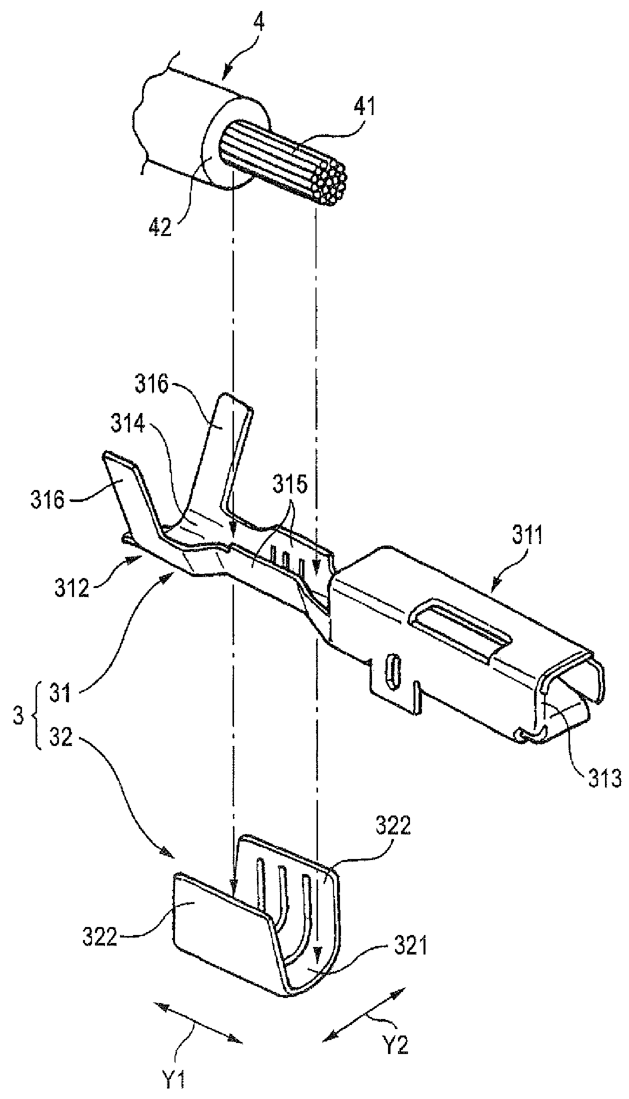
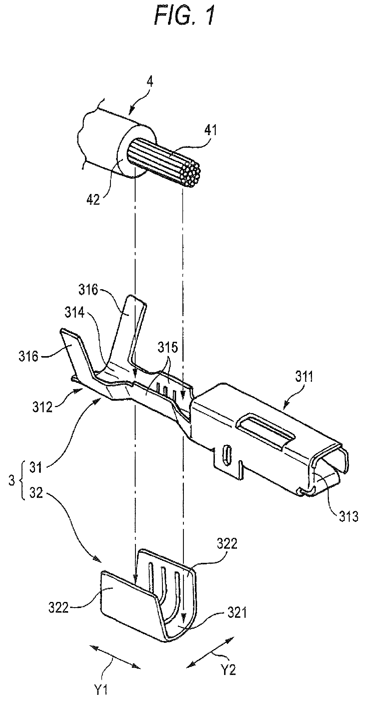
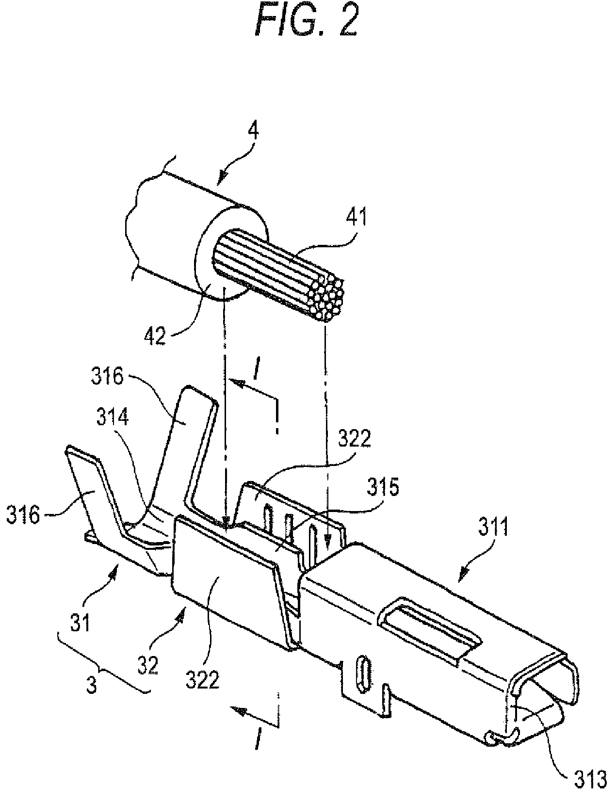
[0042]One embodiment of the present invention will be described below with reference to the drawings. FIG. 1 is a perspective view showing a terminal fitting 3 and an electric wire 4 mounted on this terminal fitting 3 according to the invention. FIG. 2 is a perspective view showing a state where a terminal fitting main body 31 is positioned in an aluminum (herein after abbreviated as Al) terminal 32 in FIG. 1. FIG. 3 is a cross-sectional view of the terminal fitting 3 and the electric wire 4, taken along the line I-I as shown in FIG. 2. FIG. 4 is a perspective view showing a state where the caulking pieces 322 of the Al terminal 32 as shown in FIG. 2 are caulked. FIG. 5 is a cross-sectional view of the terminal fitting 3 and the electric wire 4, taken along the line II-II as shown in FIG. 4.

[0043]FIG. 6 is one example of a crimping device 1 for crimping the terminal fitting 3 and the Al core wire 41 as shown in FIG. 1. FIG. 7 is an explanatory view showing a state where an anvil 19 ...


PUM


Abstract

An aluminum (Al) terminal has a first bottom wall, and a pair of caulking pieces that are stood from the first bottom wall and caulked in a state where the first bottom wall covers a wire connection portion with the core wires arranged on the upper side from the underside. Thereby, the Al terminal made of Al or Al alloy can be crimped from outside the terminal fitting main body made of copper or copper alloy, and the spring back of the terminal fitting main body made of copper or copper alloy can be suppressed by the Al terminal.

Description

BACKGROUND OF THE INVENTION[0001]1. Field of the Invention[0002]The present invention relates to a terminal fitting and a mounting method, and more particularly to a terminal fitting that is mounted on the core wires made of aluminum or aluminum alloy and its mounting method.[0003]2. Related Art[0004]Various kinds of electronic devices are mounted on an automobile as a mobile unit. The automobile has arranged a wire harness for passing electric power through a wire from a battery etc. or a control signal from a control unit to the electronic devices. The wire harness comprises an electric wire and a connector. The connector comprises a housing formed of synthetic resin having insulating property and a terminal fitting accommodated within the housing and mounted at the terminal of the electric wire.[0005]One example of the terminal fitting is shown in FIG. 10. FIG. 11 is a perspective view showing a state where the terminal fitting as shown in FIG. 10 is mounted on the electric wire....

Claims


Application Information

Patent Timeline
Patent Type & Authority Patents(United States)
IPC IPC(8): H01R4/10
CPCH01R4/185H01R13/03H01R4/62
Inventor KAKUTA, NAOKI
Owner YAZAKI CORP
Why Eureka
Try Eureka