breaker

A technology for circuit breakers and moving pieces, applied to circuits, contacts, electrical components, etc., can solve the problems of incomplete inspection of the manufacturing process, wide operating temperature bandwidth, and difficulty in temperature setting, so as to realize miniaturization, suppress damage, properly maintained effect

Inactive Publication Date: 2015-10-21
KOMATSULITE MFG
View PDF6 Cites 0 Cited by
  • Summary
  • Abstract
  • Description
  • Claims
  • Application Information

AI Technical Summary

Problems solved by technology

The protection circuits using these safety devices have the following disadvantages: the bandwidth of the operating temperature is wide, the precise temperature setting is difficult, or, because it cannot be used many times, it cannot be fully inspected in the manufacturing process.

Method used


Image

  • breaker
  • breaker
  • breaker

Examples


Embodiment Construction

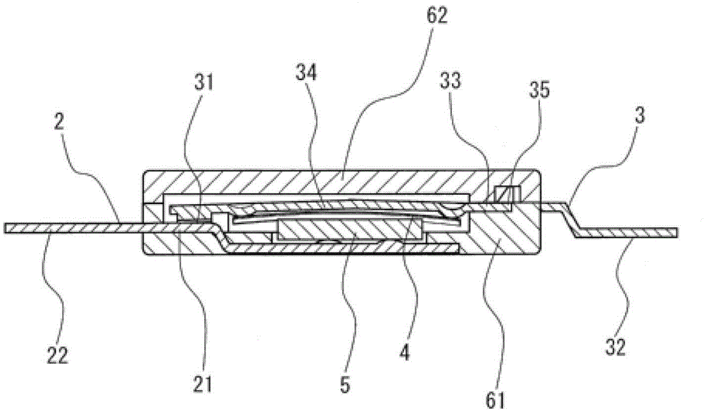
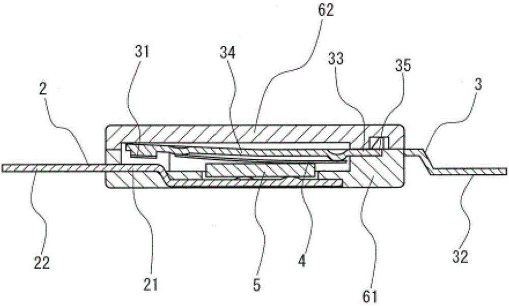
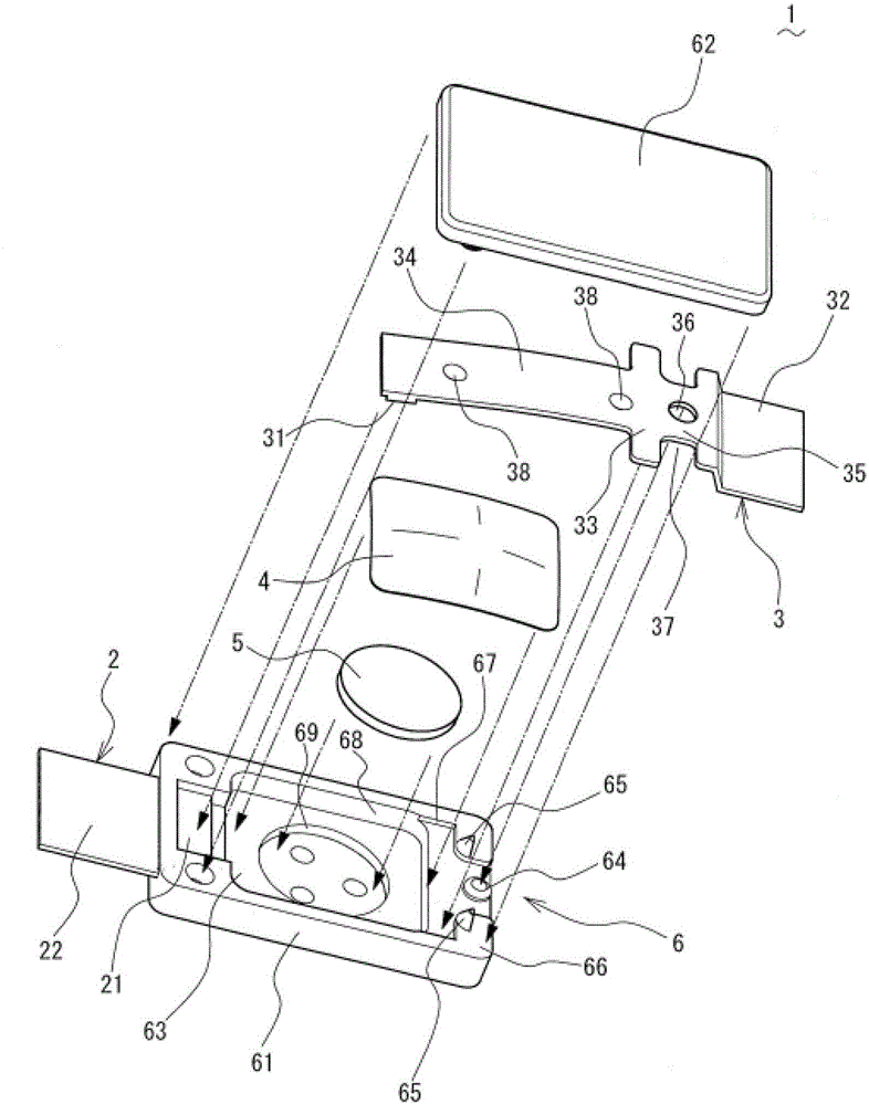
[0043] A circuit breaker according to one embodiment of the present invention will be described with reference to the drawings. figure 1 as well as figure 2 Shows the structure of the circuit breaker. The circuit breaker 1 includes: a fixed piece 2 with a fixed contact 21; a movable piece 3 with a movable contact 31 at the front end; a thermal response element 4 that deforms with temperature changes; a PTC (positive temperature coefficient) thermal sensor Resistor 5; box body 6 for accommodating fixed piece 2, movable piece 3, thermal response element 4 and PTC thermistor 5, etc. The case 6 is composed of a case main body 61 , a cover member 62 mounted on the upper surface of the case main body 61 , and the like.

[0044]The fixed piece 2 is formed by stamping a metal plate mainly composed of phosphor bronze (it can also be a metal plate such as copper-titanium alloy, nickel brass, brass, etc.), and is formed by insert molding or caulking. It is assembled into the box main...


PUM


Abstract

[Problems] Providing a compact breaker which enables to reduce contact resistance and to miniaturization much more by maintaining contact positions of a stationary contact and a movable contact appropriately. [Means to solve the Problems] In a breaker comprising a stationary piece 2, a movable piece 3, a bimetal 4 and a case 6, the movable piece 3 has a second elastic portion 35 having an elastic coefficient lower than that of a first elastic portion 34, and is fixed on the case 6 at a fixation portion 33 between the first elastic portion 34 and the second elastic portion 35.

Description

technical field [0001] The present invention relates to a small circuit breaker built in a secondary battery. Background technique [0002] Conventionally, safety devices for secondary batteries such as small nickel-hydrogen batteries and lithium-ion batteries installed in mobile phones, notebook computers, etc. have used PTC thermistors (those whose resistance value increases sharply above a certain temperature) Conductive substances) and thermal fuses, etc. The protective circuits using these safety devices have the following disadvantages: the operating temperature range is wide, precise temperature setting is difficult, or they cannot be fully inspected in the manufacturing process because they cannot be used many times. Therefore, instead of such a conventional protection circuit, a mechanically actuated safety device that can set a precise operating temperature and withstand repeated use has been expected, and various technical proposals have been made. [0003] For ...

Claims


Application Information

Patent Timeline
Patent Type & Authority Patents(China)
IPC IPC(8): H01H37/54H01H37/04
CPCH01H37/04H01H1/504H01H37/14H01H37/5427H01H1/58
Inventor 中西义博八木孝太
Owner KOMATSULITE MFG
Why Eureka
Try Eureka