

A dual-chamber membrane capacitive deionization device
A membrane capacitance deionization, dual-chamber technology, applied in electrodialysis, general water supply saving, etc., can solve the problems of high desalination energy consumption, large mass transfer resistance, poor desalination effect, etc., to improve desalination efficiency and low energy consumption. The effect of desalination and energy reduction
- Summary
- Abstract
- Description
- Claims
- Application Information
AI Technical Summary
Problems solved by technology
Method used
Image

Examples
Embodiment 1
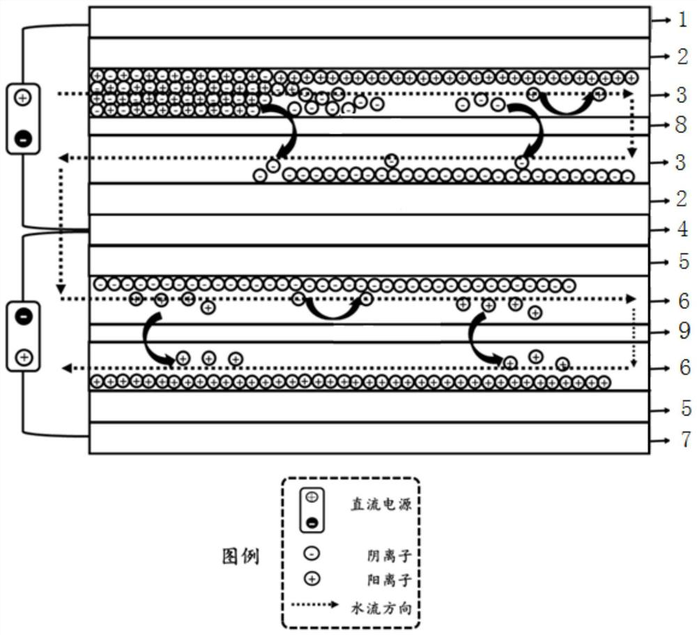
[0024] Such as figure 2 As shown, the present invention provides a double-chamber membrane capacitive deionization device, the deionization device is a double-chamber structure, the first chamber and the second chamber are at the upper and lower ends of the anion / cation exchange membrane Water flow channel diaphragms are arranged respectively, so that the raw water flows in a serpentine shape in the water flow channel diaphragms of the double chambers. Specifically, the first chamber includes a first collector electrode 1, a first electrode material 2, a first diaphragm 3, an anion exchange membrane 8, a first diaphragm 3, a first electrode material 2 and a common collector stacked up and down in sequence. The electrode 4; the second chamber includes the common collector 4, the second electrode material 5, the second diaphragm 6, the cation exchange membrane 9, the second diaphragm 6, the second electrode material 5 and the motor stacked up and down in sequence and the secon...
Embodiment 2
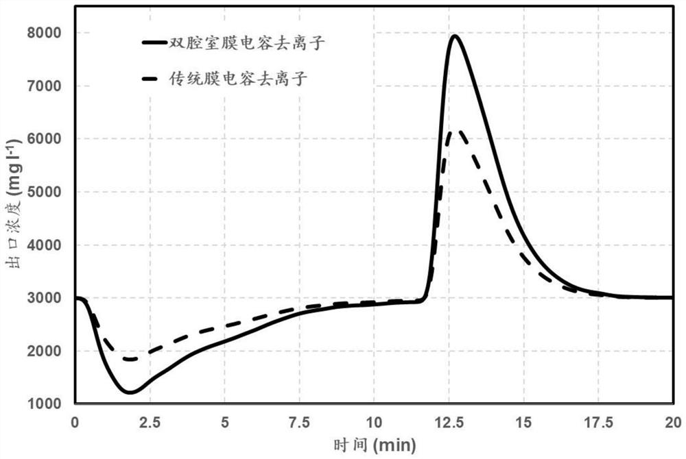
[0027]Utilize the constant flow pump to pass the NaCl solution of 3000mg / L concentration from the water storage tank of 20L through the upper end first diaphragm of the first chamber described in embodiment 1, and be positioned at the second diaphragm water outlet of lower end in the second chamber Measure the conductivity and convert it into concentration. When the concentration of the water outlet is stable, apply a DC voltage of 1.2V between the three collectors. When the concentration returns to the initial concentration again, it is the adsorption cycle. At this time, the collectors are short-circuited. The concentration changes during the treatment process are as follows image 3 As shown by the solid line in image 3 The dotted line in is the conductivity change curve of the traditional membrane capacitive deionization membrane during the desalination process.
[0028] image 3 The data shows that the ion concentration of the two devices began to decrease after the ap...
Embodiment 3
[0030] The inventor simply enlarged the scale of the device in Example 1, and carried out a multi-module performance test (10 groups): 10 groups of double-chamber membrane capacitive deionization devices described in Embodiment 1 were connected in series, and 10 groups of traditional membrane The capacitive deionization devices are connected in series, and the NaCl solution with a concentration of 1000, 2000, and 3000 mg / L is passed through 10 sets of double-chamber membrane capacitive deionization device series modules and traditional membrane capacitive deionization from a 20L water storage tank by using a constant flow pump. The device connects the modules in series, and measures the conductivity at the water outlet and converts it into a concentration. When the concentration of the water outlet is stable, a DC voltage of 1.2V is applied between the three collectors, and the current during the process is tested between the modules. and voltage (for calculating energy consump...
PUM
| Property | Measurement | Unit |
|---|---|---|
| thickness | aaaaa | aaaaa |
Abstract
Description
Claims
Application Information