

Filter bag structure
A structure and filter cloth technology, which is applied in the direction of filtration separation, membrane filter, and dispersed particle filtration, etc., can solve the problem of reducing the efficiency of dust dusting, prone to damage, and hindering the improvement of the service life of the filter cloth F energy-saving filter cloth F and other problems, to achieve the effect of improving the efficiency of dust removal and suppressing contact resistance
- Summary
- Abstract
- Description
- Claims
- Application Information
AI Technical Summary
Problems solved by technology
Method used
Image

Examples
Embodiment Construction
[0052] Hereinafter, embodiment of the filter cloth structure of this invention is demonstrated based on drawing.
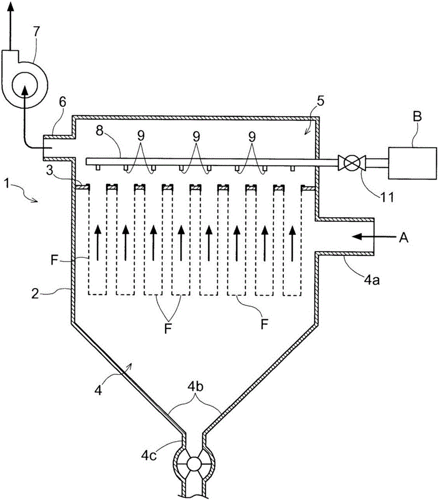
[0053] figure 1 and figure 2 A dust collector to which the filter cloth structure of the present invention is applied is shown in .
[0054] In this dust collector, the inside of the housing 2 is divided into a dusty air introduction chamber 4 (also referred to as a polluted side) and a clean air chamber 5 (also referred to as a clean side) by a partition wall 3 .
[0055] The dust-laden air introduction chamber 4 has a cone-shaped falling dust receiving portion 4b at the lower portion, and a falling dust discharge port 4c is provided at the bottom of the tapered falling dust receiving portion 4b.
[0056] In addition, a dust-laden air introduction port 4 a for introducing dust-laden air A into the dust-laden air introduction chamber 4 is provided on a side portion of the dust-laden air introduction chamber 4 .
[0057] A clean air suction pipe 6 including a s...
PUM
 Abstract
Description
Claims
Application Information