Electrical connecting apparatus

a technology of electrical connection and electrical connection device, which is applied in the direction of fixed connection, coupling device connection, instruments, etc., can solve the problems of difficult stabilization of electrical connection property between the electrical connection unit and the electrode (the upper electrode and the lower electrode) and large contact resistance, and achieve the effect of suppressing contact resistance and stable electrical connection property

Pending Publication Date: 2022-05-12
NIHON MICRONICS
View PDF0 Cites 0 Cited by
  • Summary
  • Abstract
  • Description
  • Claims
  • Application Information

AI Technical Summary

Benefits of technology

[0014]According to the present disclosure, a stable electrical connecting property can be realized by expanding a contact area between an electrode region of a wiring substrate and a connector, and suppressing contact resistance.

Problems solved by technology

However, a probe card of the prior art has a problem in that a contact area between a connector and electrodes (an upper electrode and a lower electrode) is small, and thus contact resistance becomes large, since tips of the upper end and the lower end of the connector have, for example, conical shapes or the like.
However, a projecting contact part that corresponds to the shape of the hole part in which the liquid metal is disposed must be provided, and thus an electrical connecting structure between the connector and the electrode region becomes complicated.
Thus, there is a problem in that stabilization of an electrical connecting property between each connector of the electrical connecting unit and the electrodes (the upper electrode and the lower electrode) is difficult.

Method used


Image

  • Electrical connecting apparatus
  • Electrical connecting apparatus
  • Electrical connecting apparatus

Examples


first embodiment

(B-3) Effect of First Embodiment

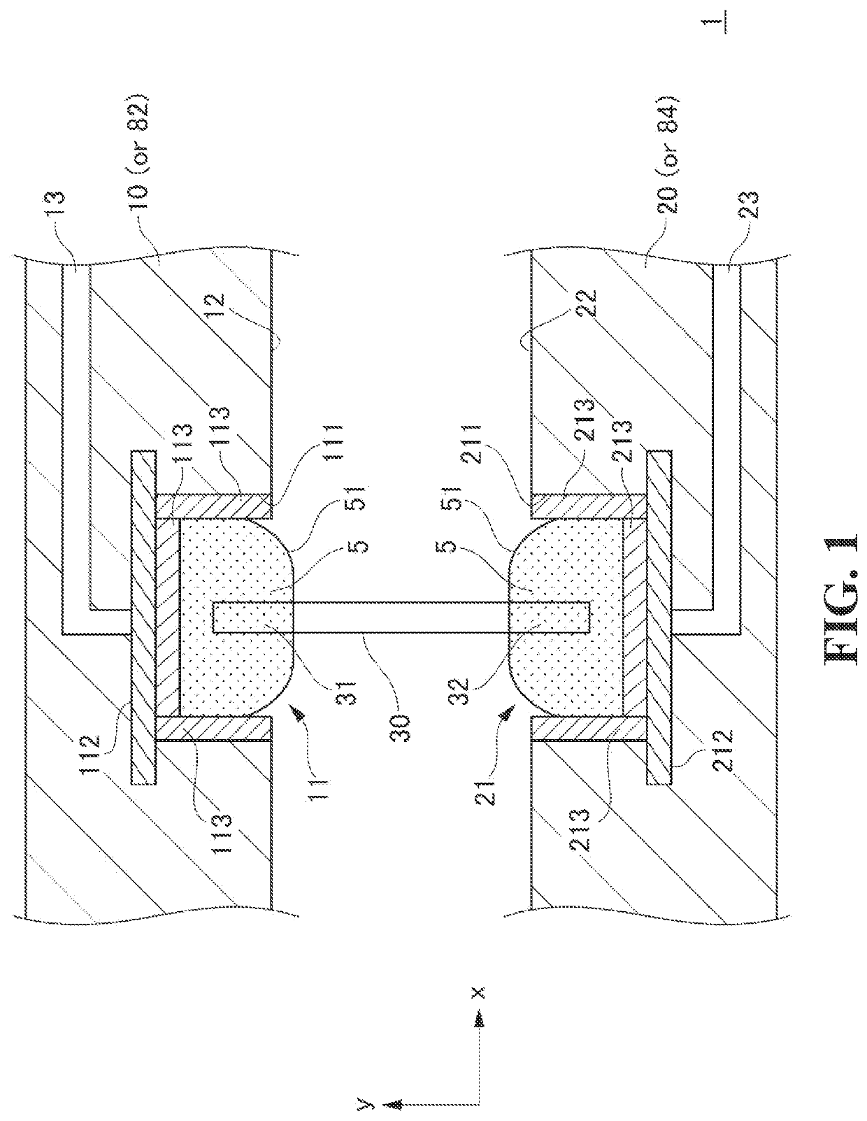
[0093]As described above, according to the first embodiment, by bringing both ends of the connector into contact with the liquid metals in the electrode region of the wiring substrate and in the electrode region of the probe substrate, a contact area between the liquid metal and the connector can be expanded, and contact resistance can be suppressed. As a result, an electrical connecting property between the connector and the electrode regions can be stabilized.

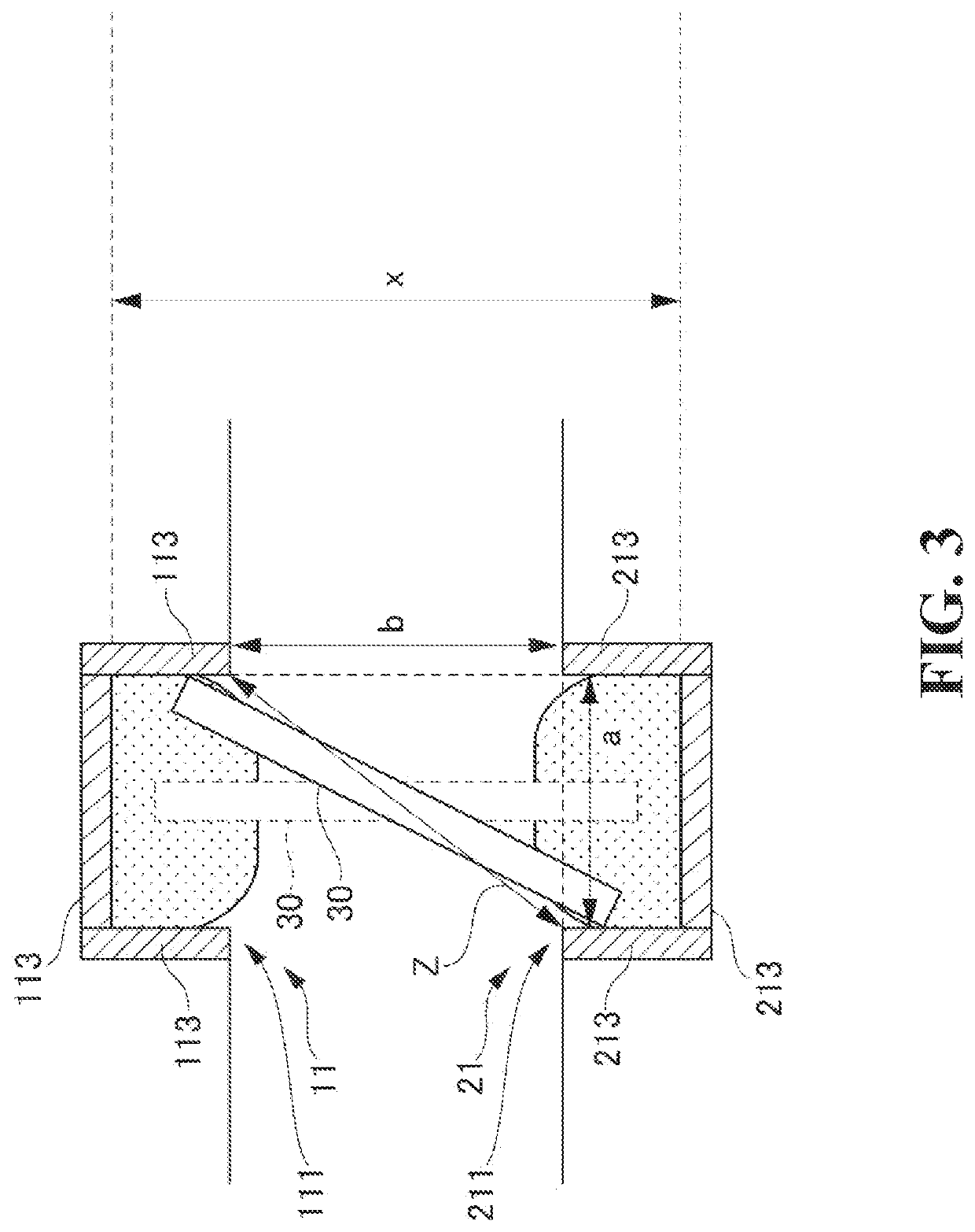
[0094]In addition, according to the first embodiment, by characterizing the shape, the length, and the like of the connector, the connector can be brought into contact with the liquid metal in a state receiving buoyancy of the liquid metals of the electrode regions. Accordingly, a stable electrical connecting property can be retained even if variations may occur in the length of the distance between the electrode regions.

(C) Other Embodiment

[0095]Although various modified embodiments were refer...


PUM

PropertyMeasurementUnit
temperatureaaaaaaaaaa
melting pointaaaaaaaaaa
conductionaaaaaaaaaa

Abstract

[Problem] To provide an electrical connecting apparatus that can realize a stable electrical connecting property by expanding a contact area between an electrode region of a wiring substrate and a connector as compared to the prior art, and suppressing contact resistance.[Solution] An electrical connecting apparatus according to the present disclosure is characterized in including a first electrode region in which a liquid metal is filled in a first recessed part that is capable of conducting with a substrate electrode of a first wiring substrate, a second electrode region in which a liquid metal is filled in a second recessed part that is capable of conducting with a substrate electrode of a second wiring substrate opposing the first wiring substrate, and a connector that causes conduction between the first electrode region and the second electrode region by bringing one end part into contact with the liquid metal of the first electrode region and bringing the other end part into contact with the liquid metal of the second electrode region.

Description

CROSS-REFERENCE TO RELATED APPLICATIONS[0001]The present application claims, under 35 USC 119, priority of Japanese Patent Application No. 2019-043733 filed on Mar. 11, 2019.TECHNICAL FIELD[0002]The present disclosure relates to an electrical connecting apparatus.BACKGROUND ART[0003]An inspection object such as an integrated circuit formed on a wafer is electrically inspected as to whether it has a predetermined electrical characteristic. Such electrical inspection is performed by using a probe card that electrically connects an electrode terminal of an inspection object with a connection terminal in an electric circuit of an inspection device.[0004]As illustrated in FIG. 6, a probe card 70 of the prior art includes a wiring substrate 72 that is electrically connected with an inspection device (not illustrated), an electrical connecting unit 73 that is disposed on the underside of the wiring substrate 72, a probe substrate 74 that is electrically connected with the wiring substrate ...

Claims


Application Information

Patent Timeline
Patent Type & Authority Applications(United States)
IPC IPC(8): H01R12/52G01R1/073G01R31/28
CPCH01R12/52G01R31/2889G01R1/07342H01R3/08H01R12/91H01R12/718G01R1/07314G01R1/06733G01R1/06755G01R1/073
Inventor HARAKO, SHOUOTABE, NOBORUKAMIYA, HIROSHIFUKAMI, YOSHIYUKIMIZUTANI, SHOGO
Owner NIHON MICRONICS
Why Eureka
Try Eureka