
Electric dipole streamer discharge type lightning conductor

a discharge type, lightning conductor technology, applied in the installation of lighting conductors, electrical apparatus casings/cabinets/drawers, coupling device connections, etc., can solve the problems of unsatisfactory operation of lightning conductors, premature tip of rods, and complicated installation of lightning conductors

Inactive Publication Date: 2009-02-24
SUNKWANG LIGHTNING PROTECTION TECHN INST
View PDF9 Cites 24 Cited by
  • Summary
  • Abstract
  • Description
  • Claims
  • Application Information

AI Technical Summary

Benefits of technology

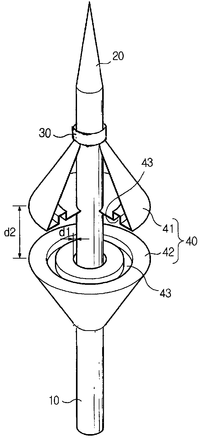
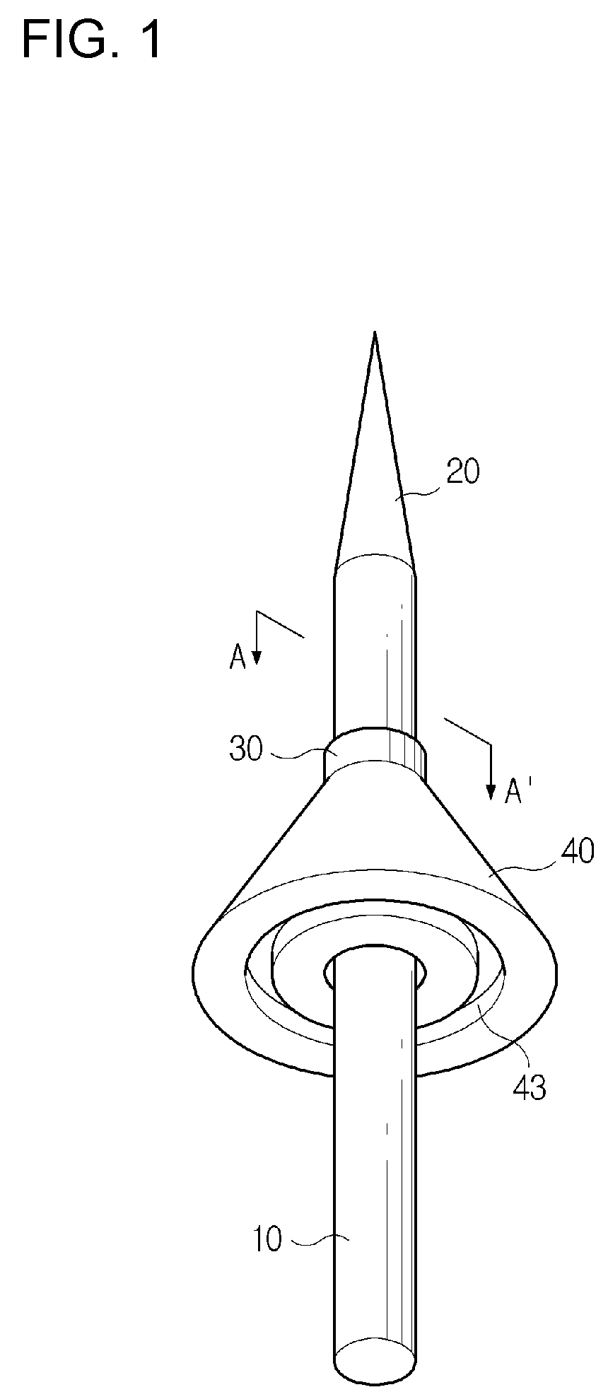
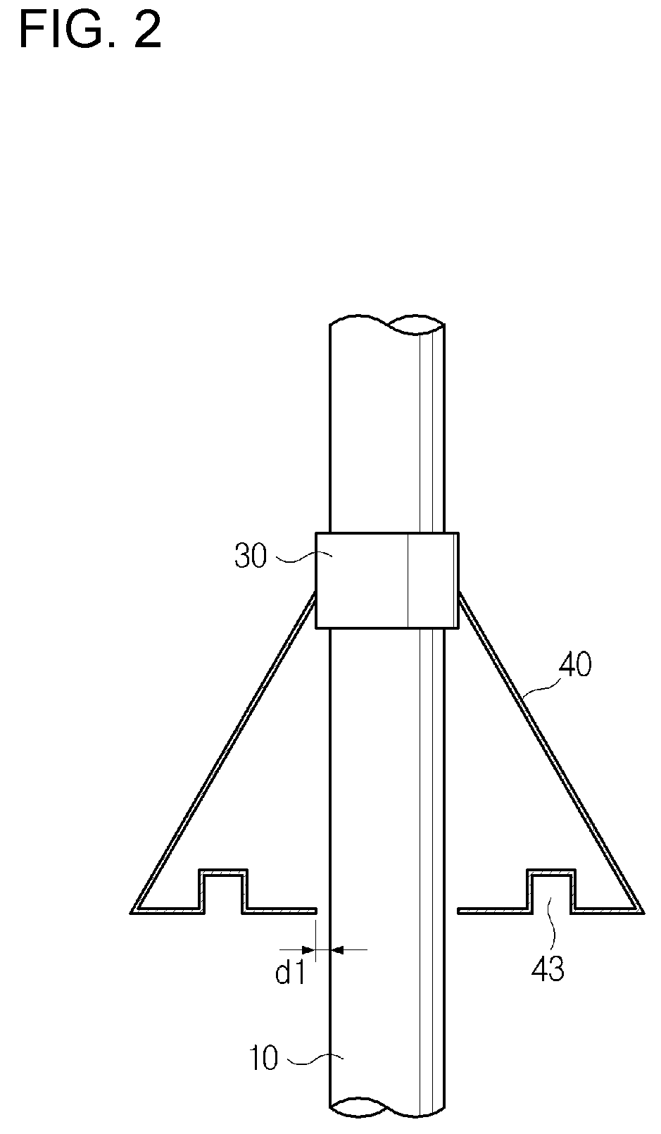
"The present invention provides an electric dipole streamer discharge type lightning conductor that can gather electric charges in the atmospheric air and generate an electric discharge due to a dielectric breakdown when a potential difference is formed between the electric charges gathered by an electric dipole and the electric charges of the earth to induce a thunderbolt. The conductor includes a body connected at a lower portion thereof to the earth, a thunderbolt receiving part, an insulating part, and a discharge inducing part. The discharge inducing part includes a first discharge inducing part and a second discharge inducing part. The first discharge inducing part has at least one groove to gather a great deal of negative electric charges, while the second discharge inducing part has one end fixed on the body and the other end spaced apart from the body to gather a great deal of positive electric charges. The first discharge inducing part carries out a dielectric breakdown due to an air gap formed by potential differences between it and the spaced body and between it and the spaced second discharge inducing part. The technical effect of this invention is to provide an effective and efficient lightning conductor for inducing thunderbolts."

Problems solved by technology

However, the sparks, which formed at both ends of the gap located between the rod and the metal cell, are generated irregularly, and formed at the tip of the rod in a premature manner.
However, the lightning conductors according to the prior arts have several problems in that it is complicated to install the lightning conductors and the lightning conductors are operated unsatisfactorily.

Method used


Image

  • Electric dipole streamer discharge type lightning conductor
  • Electric dipole streamer discharge type lightning conductor
  • Electric dipole streamer discharge type lightning conductor

Examples


example 1

[0039]Early discharge time difference inspection tests on a “high-performance lightning conductor SK-9”, which was manufactured according to the present invention, and a typical lightning conductor were carried out by Korea Electrotechnology Research Institute. A discharge time of the lightning conductor was measured after a voltage was applied under test conditions that temperature was 19.0° C., humidity was 69.0%, switching impulse applied voltage at atmospheric pressure of 993 hPa was 580 kV, applied DC voltage was 40 kV and applied waveform was 240 / 2850 μs. After that, the discharge time was converted into a standard waveform of 650 μs to obtain a discharge time difference, and then, the test result was indicated in a Table 1.

[0040]

TABLE 1Average dischargetime convertedAverageinto standardDischarge timeSpecimendischarge timewaveform of 650 μsdifferenceSK-9109.0 μs295.2 μs50.1 μsTypical lightning127.5 μs345.3 μs—conductor

[0041]As shown in Table 1, the average discharge time of th...


PUM


Abstract

Disclosed therein is an electric dipole streamer discharge type lightning conductor, which can gather electric charges in the atmospheric air at one side thereof and generate an electric discharge due to a dielectric breakdown when a potential difference is formed between the electric charges gathered by an electric dipole and the electric charges of the earth so as to emit a great deal of electric charges of the earth toward thunderclouds to thereby induce a thunderbolt.

Description

CROSS REFERENCE[0001]Applicant claims foreign priority under Paris Convention and 35 U.S.C. § 119 to Korean Patent Application No. 10-2006-0071500, filed Jul. 28, 2006 with the Korean Intellectual Property Office.BACKGROUND OF THE INVENTION[0002]1. Field of the Invention[0003]The present invention relates to an electric dipole streamer discharge type lightning conductor, which can gather electric charges in the atmospheric air at one side thereof and generate an electric discharge due to a dielectric breakdown when a potential difference is formed between the electric charges gathered by an electric dipole and the electric charges of the earth so as to emit a great deal of electric charges of the earth toward thunderclouds to thereby induce a thunderbolt.[0004]2. Background Art[0005]In general, an electromagnetic field causes a phase change in an area where thunderclouds, which induce a thunderbolt, approach. Such an electromagnetic field rises up to a range of 5 kV / m to 30 kV / m, an...

Claims


Application Information

Patent Timeline
Patent Type & Authority Patents(United States)
IPC IPC(8): H01R4/66
CPCH02G13/00H02G13/80H01T4/00
Inventor PARK, WOO-HEON
Owner SUNKWANG LIGHTNING PROTECTION TECHN INST
Learn More