Variable wave coulter

a wave coulter and wave wave technology, applied in the field of wavy coulters, can solve the problems of dumping large amounts of dir

Inactive Publication Date: 2009-03-03
BRUCE DOUGLAS G
View PDF11 Cites 23 Cited by
  • Summary
  • Abstract
  • Description
  • Claims
  • Application Information

AI Technical Summary

Benefits of technology

[0013]In practice, the waves having smaller amplitudes tend to penetrate the soil, whereas the waves of larger amplitude tend to drive the coulter in its rotation. Together, the plurality of amplitudes provides a system that is more forgiving in either wet or dry soils, and is self cleaning.

Problems solved by technology

These traditional wavy coulters are designed for only one speed, and if they go faster they throw great amounts of dirt.

Method used


Image

  • Variable wave coulter
  • Variable wave coulter
  • Variable wave coulter

Examples


second embodiment

[0044]the present invention is illustrated in FIGS. 8-15. The variable wave coulter 100 in this embodiment has three maximum amplitudes 910, 920, 930. As can be seen in FIG. 8, this embodiment may be realized by waves having crests and valleys directed in generally radial direction. However, this embodiment is not limited to this configuration, and the crests and valleys may extend back from the peripheral edge of the variable wave coulter in respective adjacent lines disposed at a predetermined acute angle with respect to the radius of the variable wave coulter 100 body as was shown in FIGS. 1, 5 and 6.

[0045]The three maximum amplitudes 910, 920, 930 are clearly seen in FIG. 9 which illustrates a segment of the periphery of the variable wave coulter 100 of this second embodiment. Crests having the largest amplitude 910, the medium amplitude 920, and the smallest amplitude 930 are shown in FIGS. 10-12, respectively.

[0046]The variable wave coulter 100 of the second embodiment is show...

third embodiment

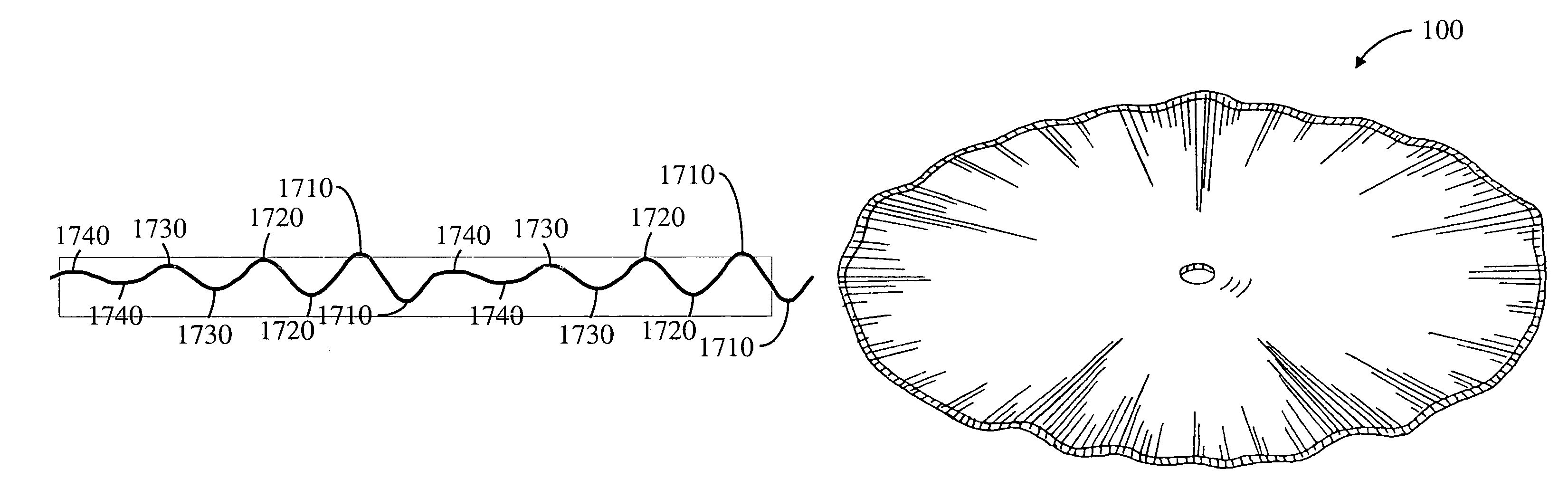
[0047]the present invention is illustrated in FIGS. 16-24. The variable wave coulter 100 in this embodiment has four maximum amplitudes 1710, 1720, 1730, 1740. As can be seen in FIG. 16, this embodiment may be realized by waves having crests and valleys directed in generally radial direction. However, this embodiment is not limited to this configuration, and the crests and valleys may extend back from the peripheral edge of the variable wave coulter 100 in respective adjacent lines disposed at a predetermined acute angle with respect to the radius of the variable wave coulter 100 body as was shown in FIGS. 1, 5 and 6.

[0048]The four maximum amplitudes 1710, 1720, 1730, 1740 are clearly seen in FIG. 17 which illustrates a segment of the periphery of the variable wave coulter 100 of this second embodiment. Crests having the largest amplitude 1710, the medium-large amplitude 1720, the medium-small amplitude 1730, and the smallest amplitude 1740 are shown in FIGS. 18-21, respectively.

[00...


PUM


Abstract

The present invention provides a wavy coulter having a plurality of variable-amplitude waves, each wave defined by a crest and an adjacent valley. The coulter is mounted on an implement such that a leading peripheral edge of the coulter rotates in a downward direction as it enters the soil. The waves having larger amplitudes of deviation from flat provide a driving force for turning the variable wave coulter. The waves having smaller amplitudes of deviation from flat provide penetration into the soil. The result is a coulter that is forgiving in both wet and dry soil conditions.

Description

CROSS REFERENCE TO RELATED APPLICATIONS[0001]Not applicable.STATEMENT REGARDING FEDERALLY SPONSORED RESEARCH OR DEVELOPMENT[0002]Not applicable.REFERENCE TO MICROFICHE APPENDIX[0003]Not applicable.BACKGROUND OF THE INVENTION[0004]1. Field of the Invention[0005]This invention relates to tillage tools and, more particularly, to a wavy coulter.[0006]2. Background Art[0007]Wavy coulters are presently used ahead of no-till implements—such as a planter—to fracture a narrow band of soil to prepare the soil to receive the no-till implement. The coulters are set at a penetrating depth of about four inches, and the amplitude of the wave from crest-to-valley is about one to two inches and generally defines the width of the band. All crests and all valleys deviate from a single plane by the same amount. These traditional wavy coulters are designed for only one speed, and if they go faster they throw great amounts of dirt.[0008]The crests and valleys on presently available wavy coulters are posi...

Claims


Application Information

Patent Timeline
Patent Type & Authority Patents(United States)
IPC IPC(8): A01B59/00
CPCA01B23/06
Inventor BRUCE, DOUGLAS G.
Owner BRUCE DOUGLAS G
Why Eureka
Try Eureka