

Boat control system with return to center steering command
- Summary
- Abstract
- Description
- Claims
- Application Information
AI Technical Summary
Benefits of technology
Problems solved by technology
Method used
Image

Examples
Embodiment Construction
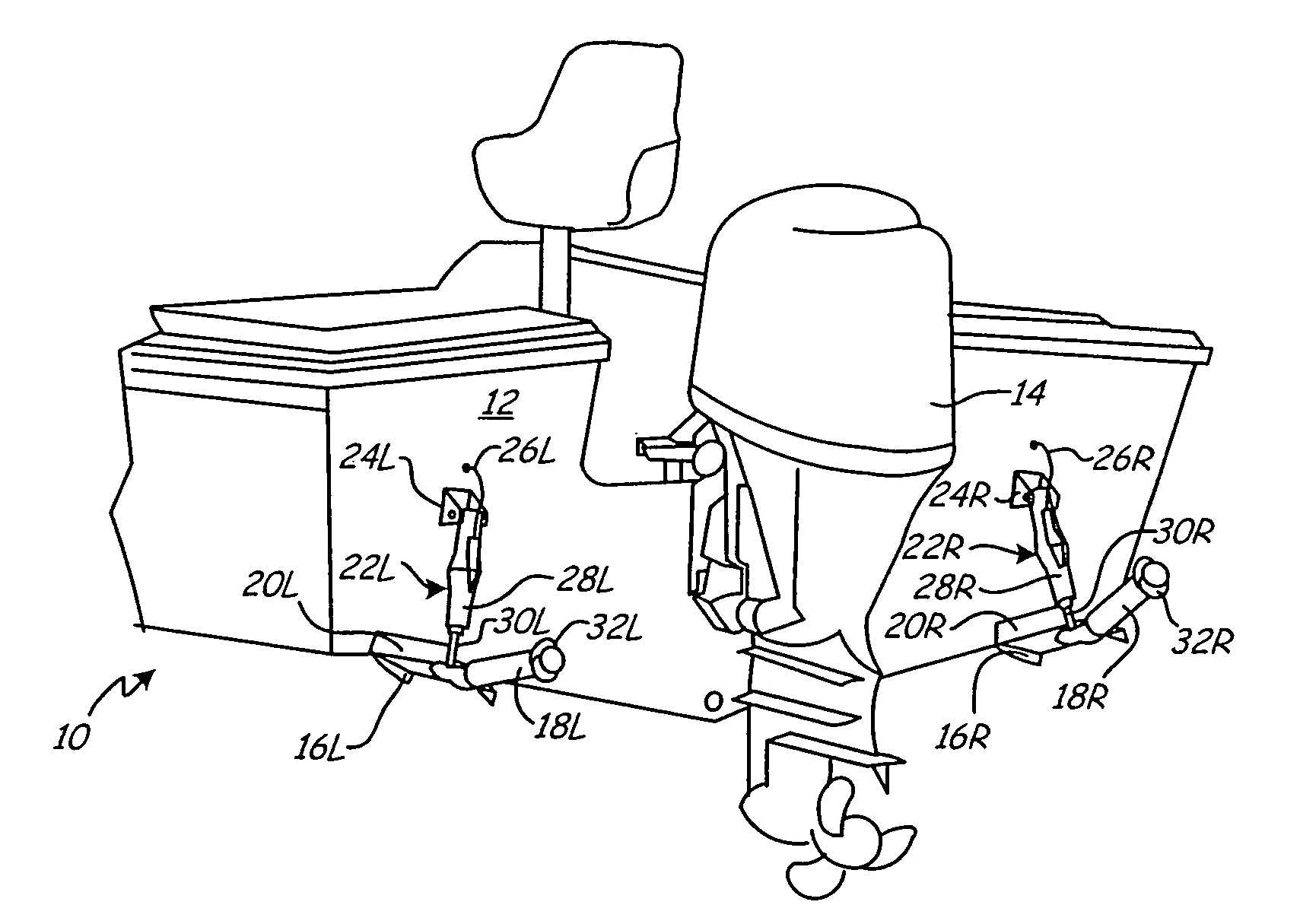
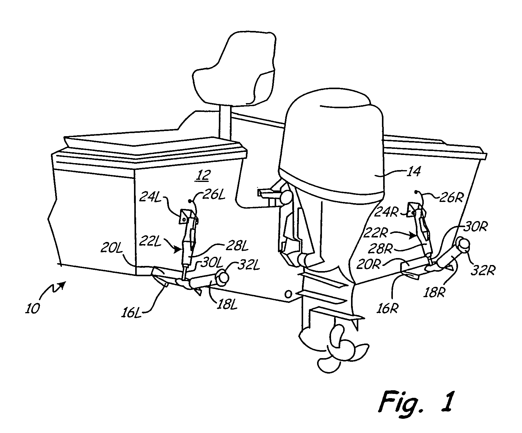
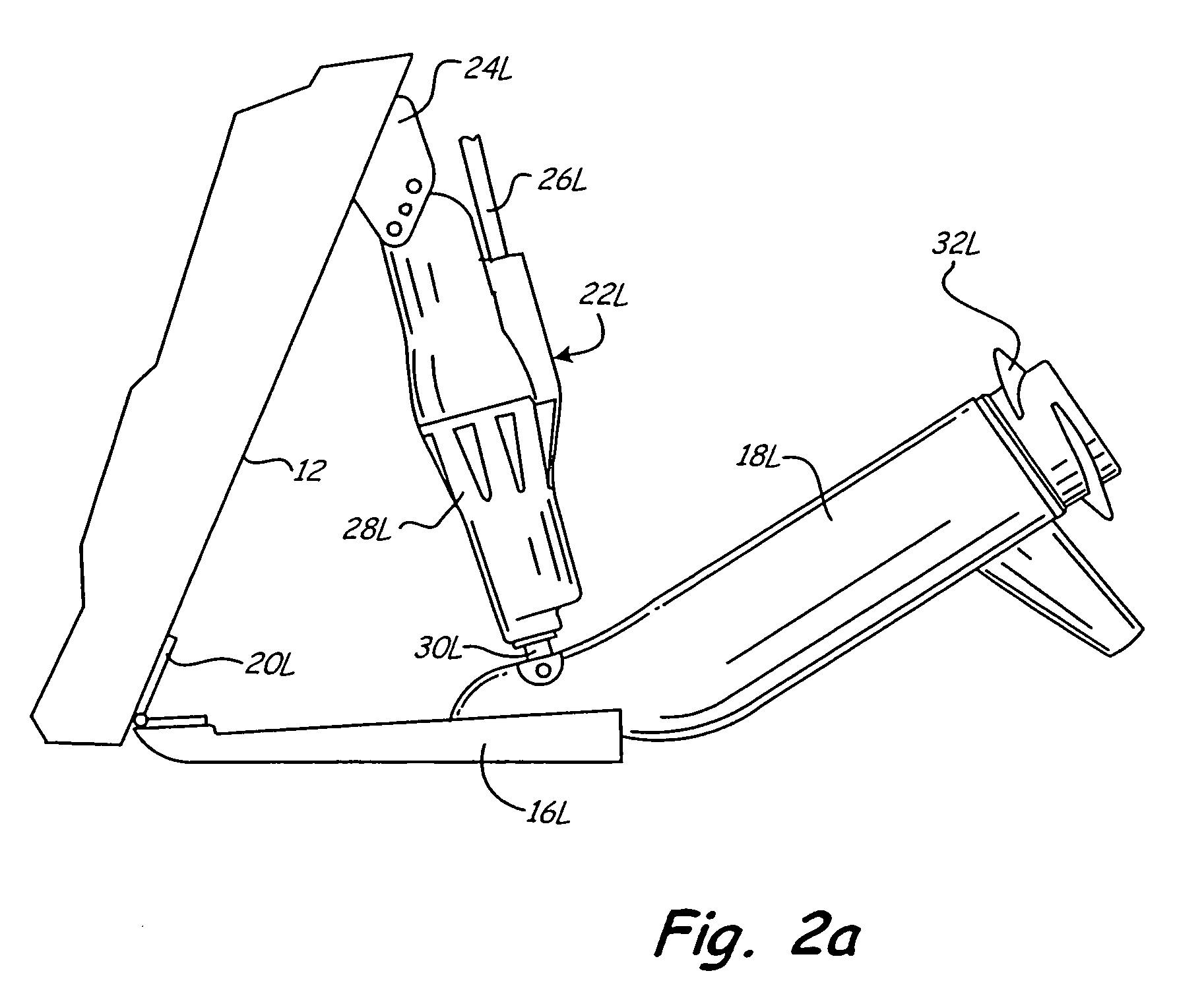
[0018]FIG. 1 shows the stern of boat 10. Mounted on transom 12 is outboard motor 14 and trim tabs 16L and 16R. Left or port trolling motor 18L is carried by left trim tab 16L, and right or starboard trolling motor 18R is carried by right trim tab 16R. Hinges 20L and 20R pivotally connect trim tab 16L and 16R, respectively, to transom 12. Linear actuators 22L and 22R are connected between brackets 24L, 24R on transom 12 and trim tabs 16L and 16R, respectively. The angle of each trim tab 16L, 16R is determined by the amount of extension of actuators 22L and 22R, respectively. Actuators 22L and 22R are, in one embodiment, electromechanical actuators that receive electrical power and provide feedback signals through cables 26L, 26R. Actuator 22L includes actuator housing 28L and actuator rod 30L; and actuator 22R includes actuator housing 28R and actuator rod 30R.
[0019]Trim tabs 16L and 16R operate in a trim range from about 0° (horizontal) to about 20° below horizontal. Trim tabs 16L a...
PUM
 Abstract
Description
Claims
Application Information