Exercise device for a vaginal muscle of a female
a vaginal muscle and exercise device technology, applied in the field of exercise devices, can solve the problems of no exercise device for vaginal muscle, pain for patients, and inability to strengthen the muscle around the vagina, so as to reduce pain, and improve the effect of vaginal exercis
- Summary
- Abstract
- Description
- Claims
- Application Information
AI Technical Summary
Benefits of technology
Problems solved by technology
Method used
Image
Examples
first embodiment
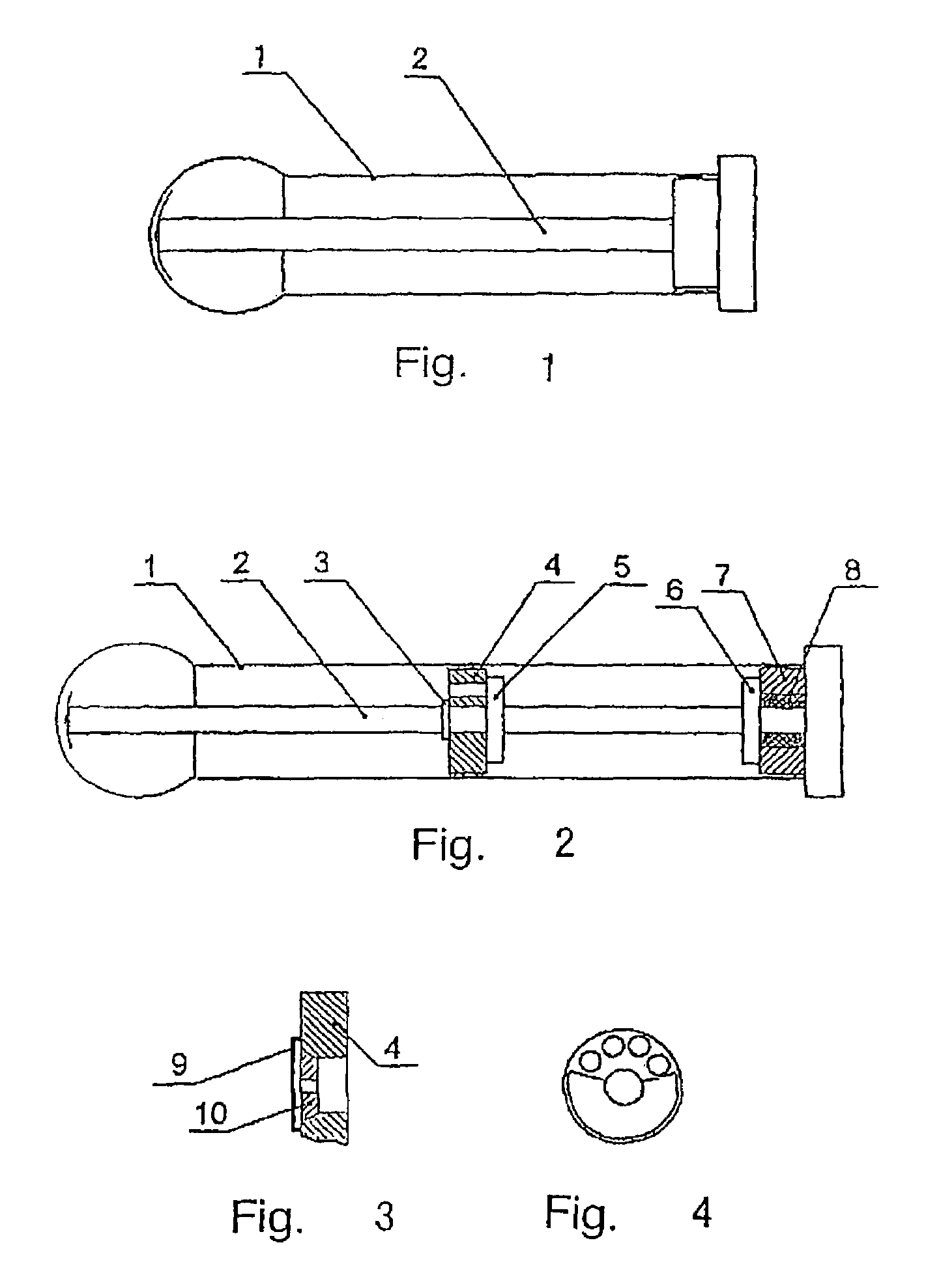
[0020]The first embodiment is illustrated in the drawing FIG. 1. The elastic tube I is cylindrical, the left end of which is formed as a hemisphere to simulate the glans. The brace 2 is a shaft, whose left end is formed as a shell and right end is conglutinated with the tube 1 to form a sealed chamber. Fluid is sealed in the chamber. The brace 2 can maintain a rigid shape of the device and make it possible for users to put the device into their vagina. When the group of vaginal muscles squeezes the tube 1, the resistance of the device comes from the elastic deformation of the tube 1 and the fluid sealed inside. The tube 1 can be made of elastic material such as rubber, silica gel or other suitable materials. The brace 2 can be made of hard material, such as engineering plastic, metals or other suitable materials. The change of the pressure which is given by the hand to the outer part of the tube 1 will effect the change of the device's resistance. Different resistance at different e...
second embodiment
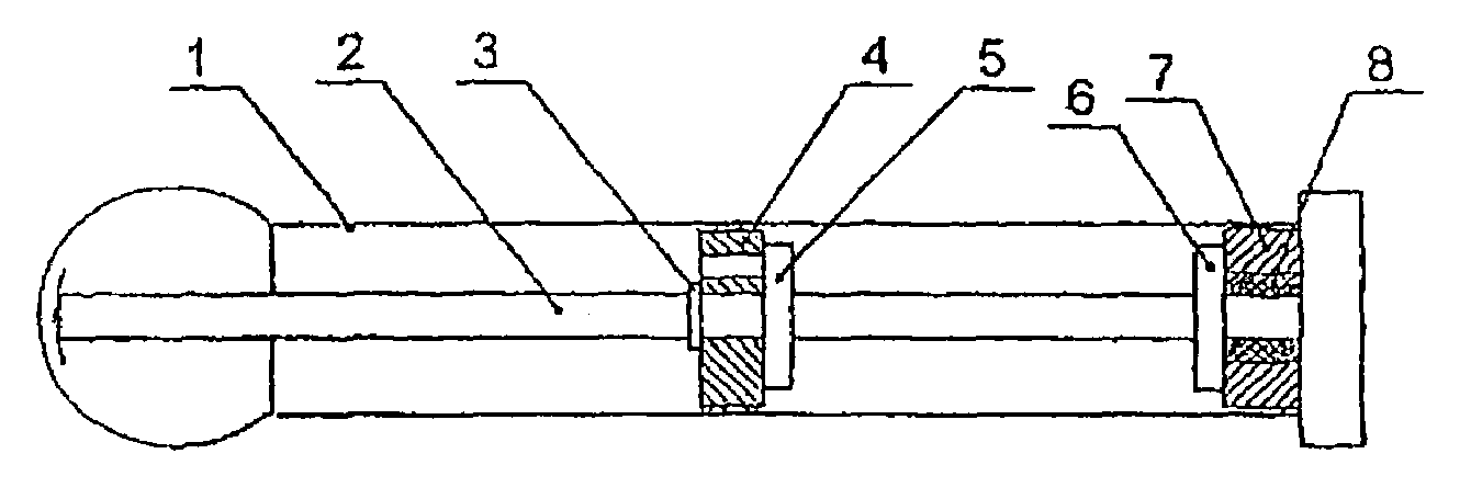
[0021]The second embodiment is illustrated in the drawing FIG. 2, 3, 4. The elastic tube 1 is conglutinated with the lid 7. They form a sealed chamber with the brace 2, the retainer 6 and the seal 8. The fluid is sealed in the chamber. The partition component 4 is conglutinated with the tube 1 on its round side. The brace 2 is a shaft, whose left end is formed as a shell to protect the tube's left end. The resistance control element 5, the first retainer 3 and the second retainer 6 are fixed on the brace 2.
[0022]The resistance control element 5 and the partition component 4 have a closely touched same-shaped interface. The resistance control element 5 has at least one gap. The partition component 4 is longitudinally fixed on the brace 2 by the first retainer 3 and the resistance control element 5. The lid 7 and the seal 8 are longitudinally fixed on the brace 2 by the second retainer 6. The seal 8 can prevent the inner fluid from leaking out while the brace 2 rotates in the lid 7. T...
third embodiment
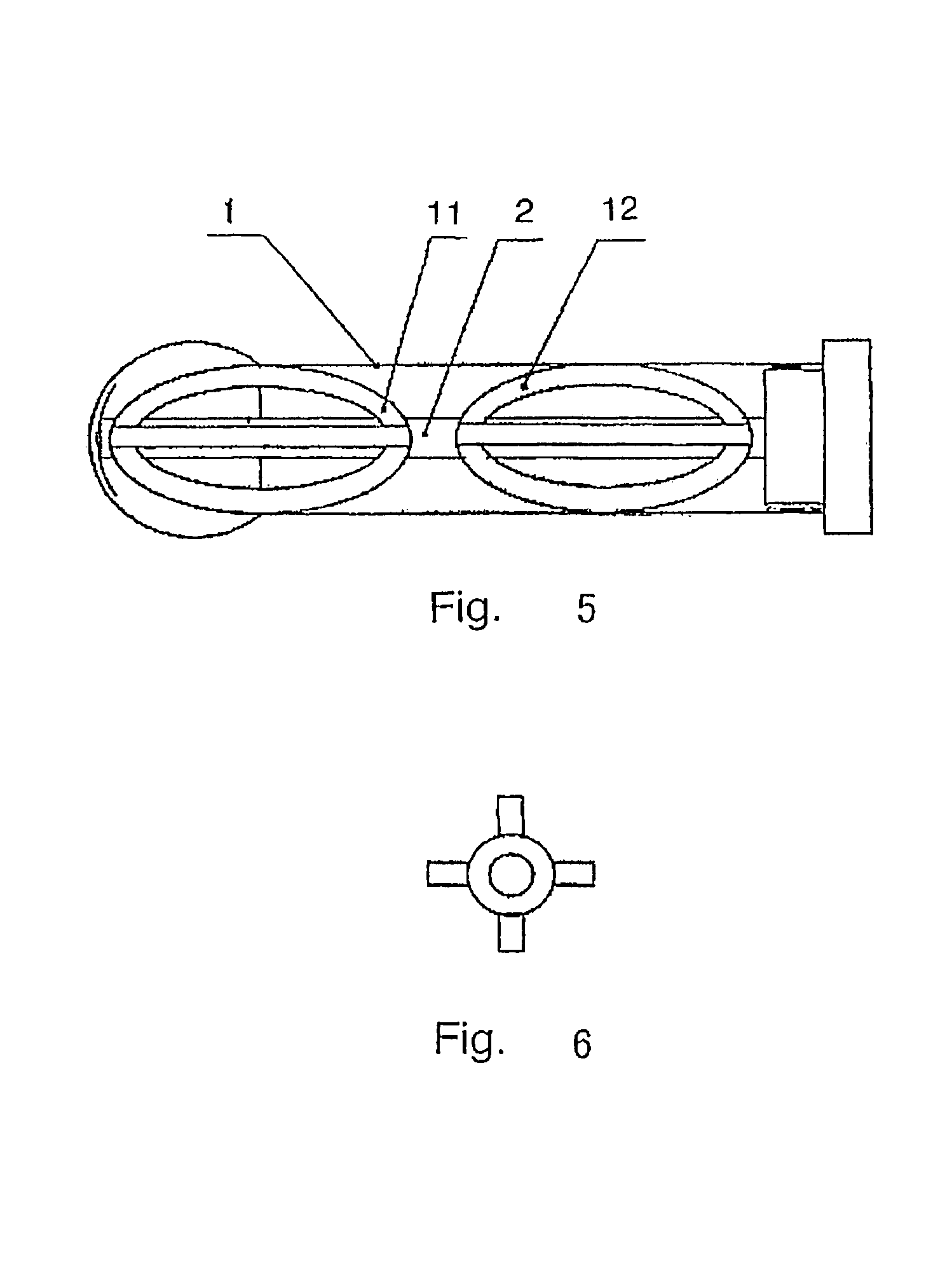
[0023]The third embodiment is illustrated in the drawing FIGS. 5 and 6. The tube 1 is conglutinated with the brace 2 at the right end. The elastic parts 11 and 12 are joined by four semi-ellipses, formed like a football. They can be made of rubber. The brace 2 goes through the center of the elastic parts 11 and 12. In this case, the resistance of the device comes from the elastic deformation of the elastic parts.
PUM
 Abstract
Description
Claims
Application Information
 - R&D
- Intellectual Property
- Life Sciences
- Materials
- Tech Scout
- Unparalleled Data Quality
- Higher Quality Content
- 60% Fewer Hallucinations
Browse by: Latest US Patents, China's latest patents, Technical Efficacy Thesaurus, Application Domain, Technology Topic, Popular Technical Reports.
© 2025 PatSnap. All rights reserved.Legal|Privacy policy|Modern Slavery Act Transparency Statement|Sitemap|About US| Contact US: help@patsnap.com


