Distortion correction circuit for generating distortion-corrected image using data for uncorrected image

a distortion correction and image technology, applied in the field of distortion correction circuits, can solve the problems of poor distortion characteristic of inexpensive optical systems

Inactive Publication Date: 2009-03-03
SOCIONEXT INC
View PDF4 Cites 11 Cited by
  • Summary
  • Abstract
  • Description
  • Claims
  • Application Information

AI Technical Summary

Problems solved by technology

The distortion characteristic of an inexpensive optical system is usually poor.

Method used


Image

  • Distortion correction circuit for generating distortion-corrected image using data for uncorrected image
  • Distortion correction circuit for generating distortion-corrected image using data for uncorrected image
  • Distortion correction circuit for generating distortion-corrected image using data for uncorrected image

Examples


first embodiment

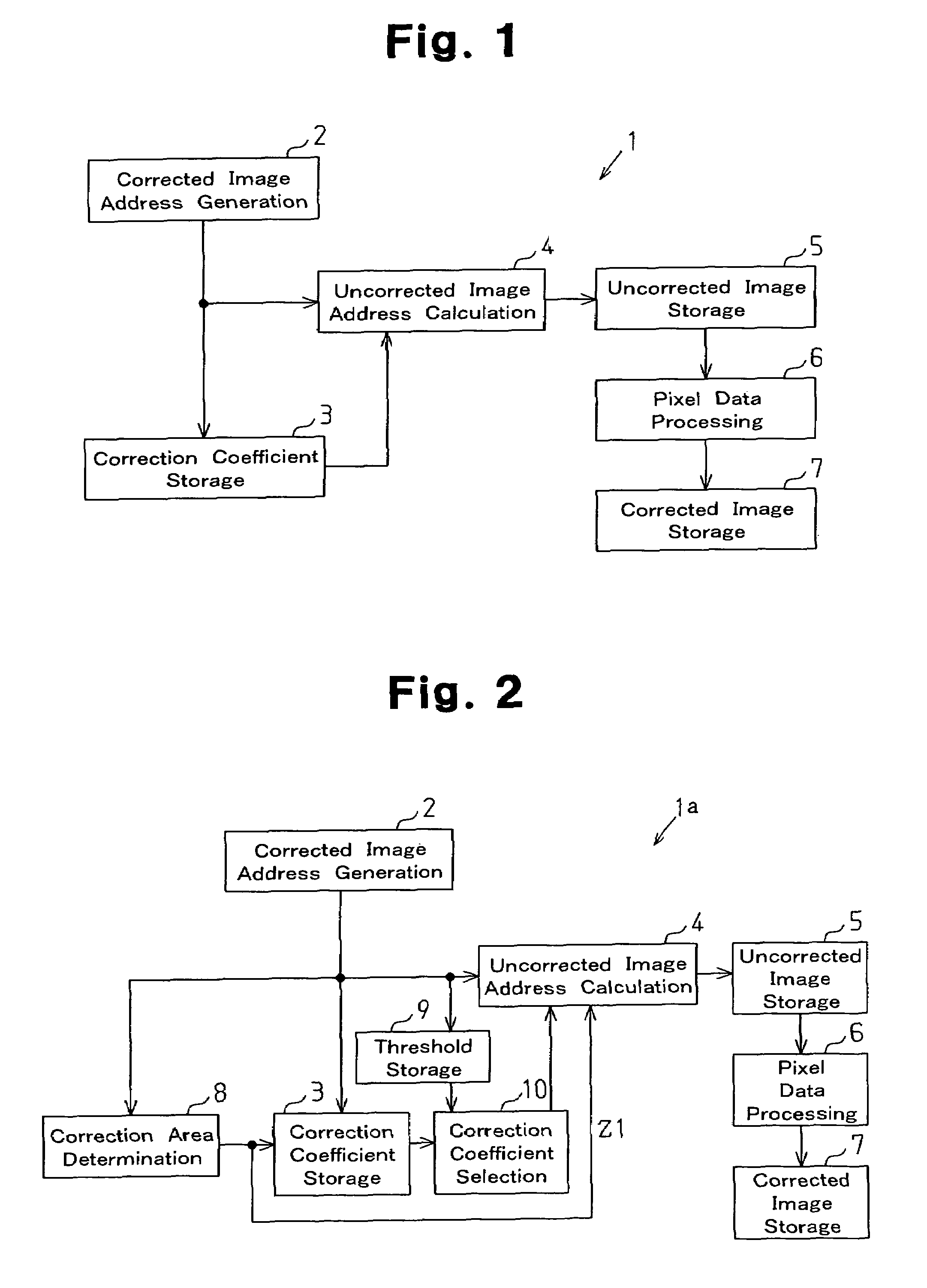
[0026]As shown in FIG. 1, a distortion correction circuit 1 according to the present invention includes a corrected image address generation circuit 2, a correction coefficient storage circuit 3, an uncorrected image address calculation circuit 4, an uncorrected image storage circuit 5, a pixel data processing circuit 6, and a corrected image storage circuit 7. In the distortion correction circuit 1, the corrected image address generation circuit 2 generates a horizontal address and a vertical address for each pixel of a corrected image. The uncorrected image address calculation circuit 4 reads a pixel pitch correction coefficient, which is associated with the horizontal and vertical addresses generated by the corrected image address generation circuit 2, from the correction coefficient storage circuit 3. The uncorrected image address calculation circuit 4 calculates the data addresses of an uncorrected image using the horizontal and vertical addresses and the pixel pitch correction...

second embodiment

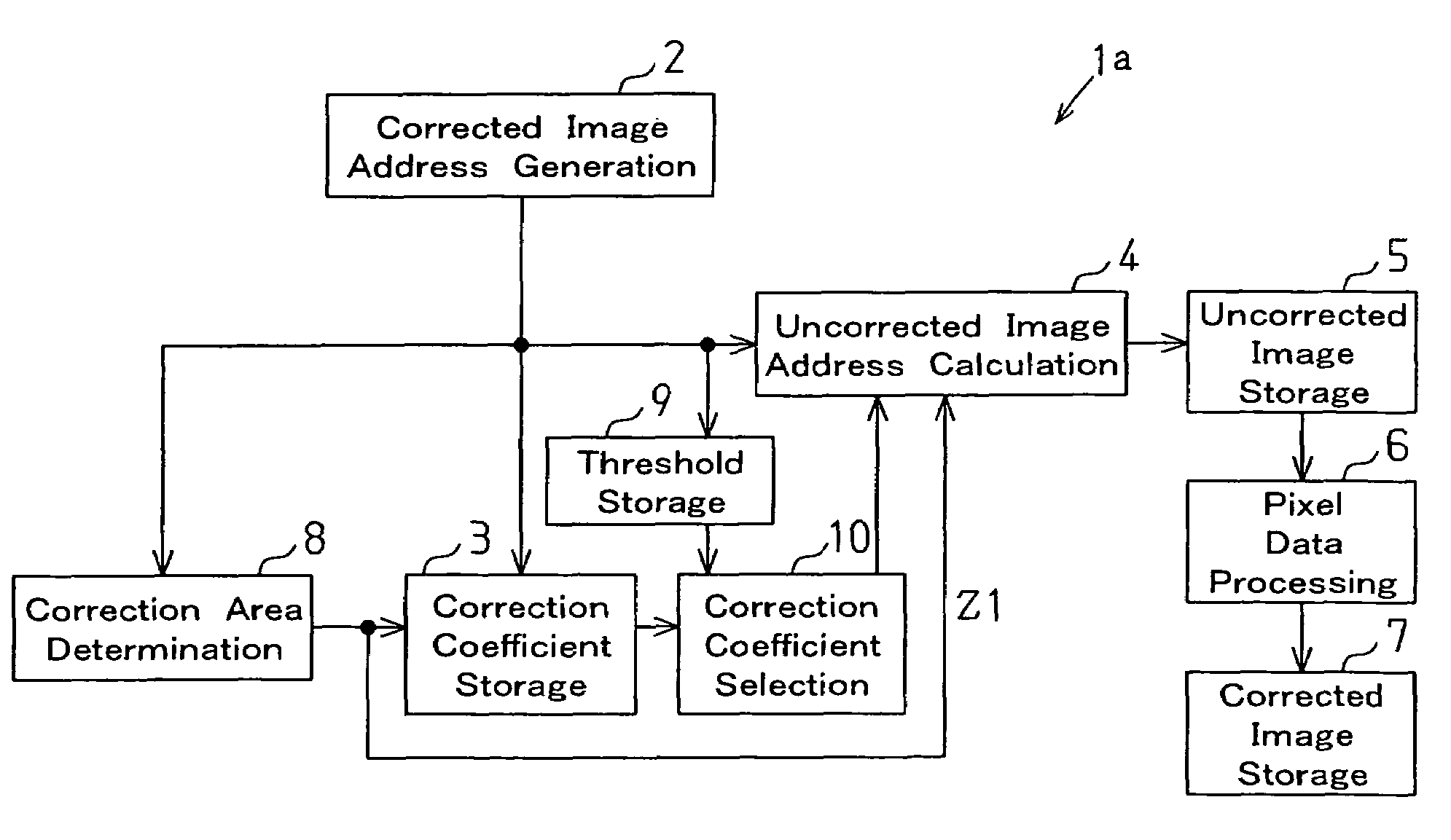
[0029]As shown in FIG. 2, a distortion correction circuit 1a according to the present invention includes a corrected image address generation circuit 2, a correction coefficient storage circuit 3, an uncorrected image address calculation circuit 4, an uncorrected image storage circuit 5, a pixel data processing circuit 6, a corrected image storage circuit 7, and a correction area determination circuit 8. The correction area determination circuit 8 determines whether the horizontal and vertical addresses generated by the corrected image address generation circuit 2 are in an area that requires correction or in an area that requires no correction. When these addresses are in an area that requires no correction, the correction area determination circuit 8 outputs a no-correction signal Z1. When receiving the no-correction signal Z1, the uncorrected image address calculation circuit 4 uses the horizontal and vertical addresses generated by the corrected image address generation circuit ...

third embodiment

[0032]The following describes a distortion correction circuit according to the present invention.

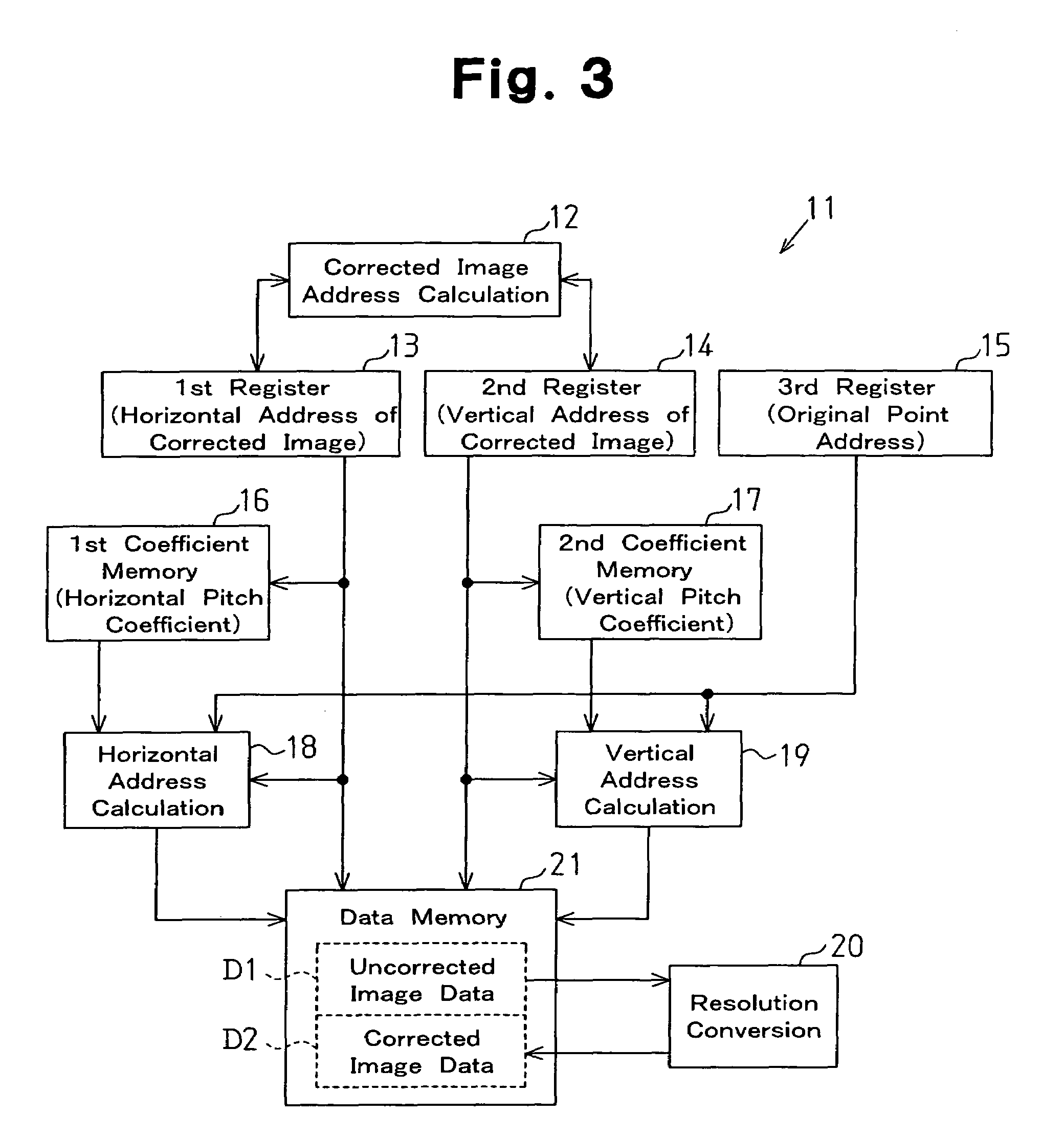
[0033]As shown in FIG. 3, a distortion correction circuit 11 according to the third embodiment is used for a digital camera, and processes data for an uncorrected image formed by an imaging device (e.g., a CCD sensor and a CMOS sensor) of the digital camera, to generate a corrected image whose distortion has been corrected. The corrected image generated by the distortion correction circuit 11 is, for example, a square image with a size of 4096×4096 pixels. To generate the corrected image, the distortion correction circuit 11 searches an uncorrected image (original image) for image data for a horizontal address and a vertical address of each pixel of the corrected image. The original image is larger than the corrected image. The original image is, for example, an image with the size of (4096+α)×(4096+α) pixels including pincushion distortion as shown in FIG. 4.

[0034]As shown in FIG. 3, th...


PUM


Abstract

A circuit for correcting distortion produced by the lens of a digital camera when generating an image, which includes pixels. The correction circuit includes an address generation circuit for generating horizontal and vertical addresses for each pixel. A coefficient storage circuit stores a pitch correction coefficient associated with the horizontal or vertical address of each pixel. A storage circuit stores data for an image for which distortion is uncorrected in association with an address of the uncorrected image. A calculation circuit calculates the address of data of the uncorrected image corresponding to each pixel using the associated horizontal and vertical addresses and pitch correction coefficient of the horizontal or vertical address. A processing circuit reads the data of the uncorrected image from the storage circuit and generates data for a distortion-corrected image.

Description

CROSS-REFERENCES TO RELATED APPLICATIONS[0001]This application is based upon and claims the benefit of priority from prior Japanese Patent Application No. 2004-033783 filed on Feb. 10, 2004, the entire contents of which are incorporated herein by reference.BACKGROUND OF THE INVENTION[0002]The present invention relates to a distortion correction circuit that retrieves data for an image to correct distortion in the image, and relates to, for example, a distortion correction circuit that corrects an image formed by an imaging device with an optical system having a distortion characteristic.[0003]In recent years, digital cameras, with an increasing number of pixels being recordable, are required to include optical systems having higher performance. For a digital camera using a built-in lens, an exclusively designed lens is used. For a digital camera using changeable lenses, various lenses, each having a unique distortion characteristic, are used. A digital camera incorporated in a mobil...

Claims


Application Information

Patent Timeline
Patent Type & Authority Patents(United States)
IPC IPC(8): H04N5/228G06T3/00H04N5/232H04N101/00
CPCH04N5/3572H04N25/61
Inventor IGA, KIICHIRO
Owner SOCIONEXT INC
Why Eureka
Try Eureka