Interferometric method and apparatus for measuring optical signal quality in optical communications system

Active Publication Date: 2009-03-03
AMERICAN TELEPHONE & TELEGRAPH CO
View PDF2 Cites 24 Cited by
  • Summary
  • Abstract
  • Description
  • Claims
  • Application Information

AI Technical Summary

Benefits of technology

[0013]The computer readable instructions may further cause the processor to determine a numerical value of an optical signal-to-noise rati

Problems solved by technology

Direct spectrum measurement using tunable filters cannot distinguish between coherent signal power and incoherent noise power.
It must rely on baseline measurements at signal-free wavelengths, but such baseline wavelengths may not be present in advanc

Method used


Image

  • Interferometric method and apparatus for measuring optical signal quality in optical communications system
  • Interferometric method and apparatus for measuring optical signal quality in optical communications system
  • Interferometric method and apparatus for measuring optical signal quality in optical communications system

Examples


Embodiment Construction

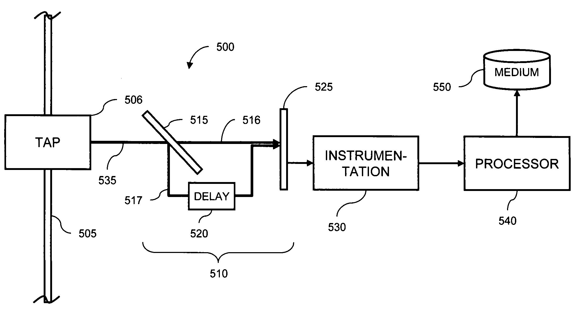
[0022]The present invention overcomes the above-described problems by determining the OSNR of signals propagating in photonic networks. By using an interferometer, the inventors distinguish between a coherent optical signal and an incoherent noise occupying the same optical band.

[0023]Interferometry of CW Light

[0024]When a continuous wave (CW) light with frequency ω and the power I0 enters a Michelson interferometer, the transmitted power IT is given by the following expression:
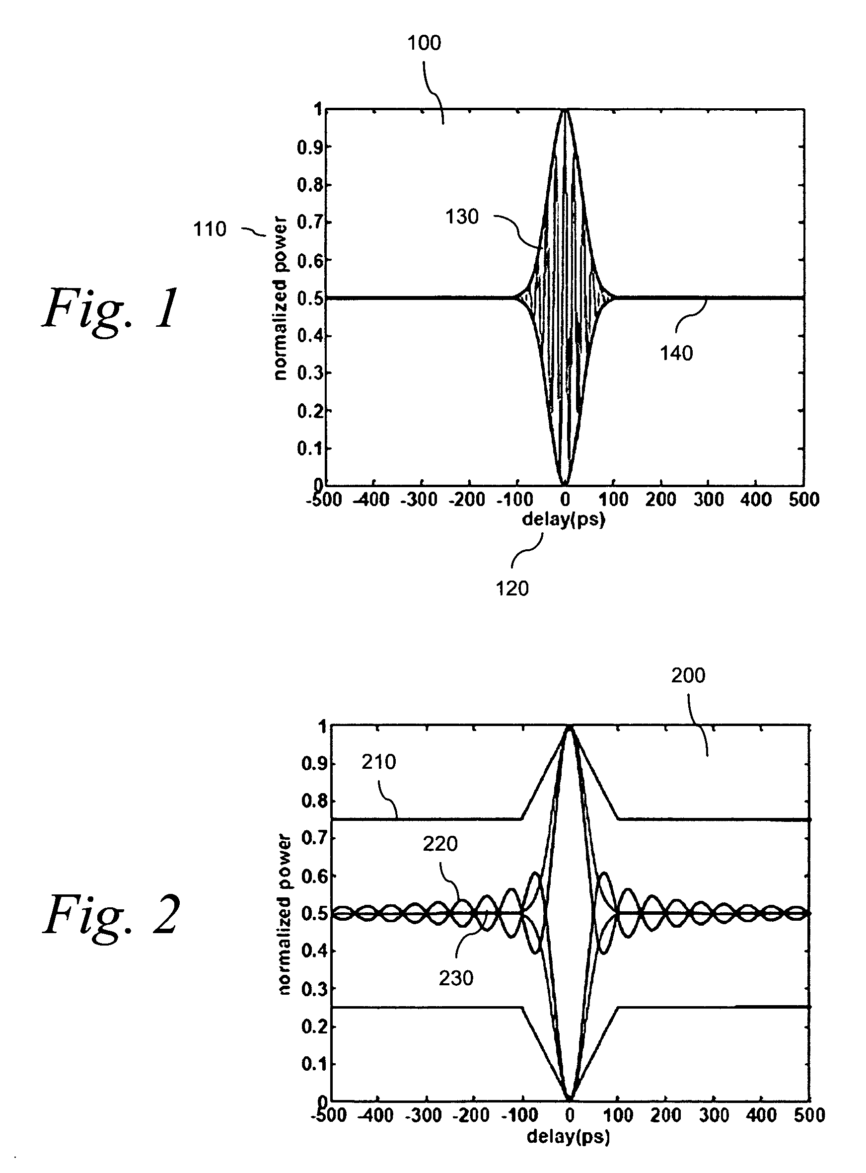
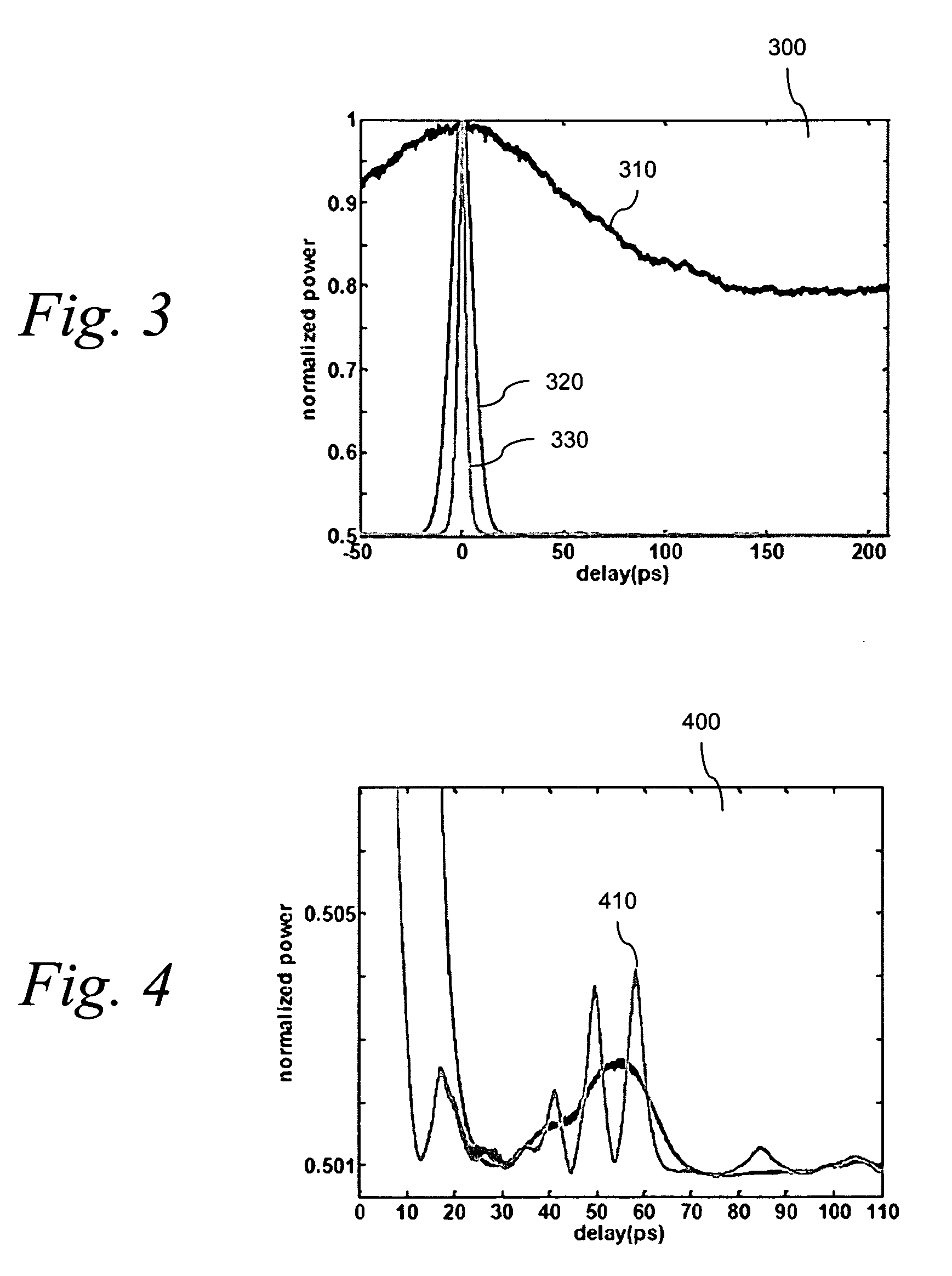
[0025]IT=I02⁢(1+cos⁢⁢ω⁢⁢τ)(1)

[0026]where τ is the delay between two arms of the interferometer expressed in units of time. A rigorous mathematical treatment is given in Hermann Haus, “Waves and Fields in Optoelectronics” at § 3.6, the content of which is incorporated by reference herein. Depending on the interferometer delay, the transmitted power oscillates between I0, corresponding to full transmission of the incident power, and zero, corresponding to total reflection of the incident light back to the input...


PUM


Abstract

Differences in the interferometric patterns of modulated telecommunication signals and broadband optical noise sources are identified and are exploited in measuring the optical signal-to-noise measurements in reconfigurable photonic networks. A light output power from said interferometer corresponding to a specified delay setting in the interferometer is measured, and a coherent optical signal is distinguished from the incoherent optical noise based on the light output power measurement.

Description

FIELD OF THE INVENTION[0001]The present invention relates generally to measuring the quality of an optical signal transmitted in a photonics network, and, more particularly, to techniques for using an interferometer to separate a modulated, coherent signal from incoherent noise mixed with the signal.BACKGROUND OF THE INVENTION[0002]As optical transmission distances become longer and photonic networks begin to assume some of the routing functions formerly associated with electronic switching, there is a need for optical performance monitoring, and optical signal-to-noise ratio (OSNR) measurement in particular.[0003]Direct spectrum measurement using tunable filters cannot distinguish between coherent signal power and incoherent noise power. It must rely on baseline measurements at signal-free wavelengths, but such baseline wavelengths may not be present in advanced networks with optical add / drop functions.[0004]Polarization-based techniques offer a way to reject a signal so that the n...

Claims


Application Information

Patent Timeline
IPC IPC(8): G01B9/02
CPCG01B9/02H04B10/07953
Inventor BRODSKY, MIKHAILFEUER, MARK DAVID
Owner AMERICAN TELEPHONE & TELEGRAPH CO
Why Eureka
Try Eureka