Arcing fault protection system for an air arc switchgear enclosure

a technology of air arc and fault protection system, which is applied in the direction of emergency protective arrangement details, emergency protective arrangement for limiting excess voltage/current, electrical apparatus, etc., can solve the problems of arcing faults, arcing faults, arcing faults, etc., and achieve rapid elimination of arcing fault currents, reduce or eliminate the generation of hot gases associated with arcing fault currents

Active Publication Date: 2009-03-03
SQUARE D CO
View PDF5 Cites 21 Cited by
  • Summary
  • Abstract
  • Description
  • Claims
  • Application Information

AI Technical Summary

Benefits of technology

[0011]In accordance with one aspect of the present invention, there is provided an arcing fault protection system for a switchgear enclosure accommodating a plurality of feeder circuits. Each of the feeder circuits is electrically connected to a source bus and carries an electric current through the switchgear enclosure toward one or more loads downstream of the switchgear enclosure. The arcing fault protection system comprises a plurality of arcing fault detectors for monitoring the feeder circuits for the presence of arcing fault currents, means for producing an arcing fault detection signal upon detecting arcing fault currents in any of the feeder circuits, and an arc diverter mechanism such as a grounding device for rapidly grounding the source bus in response to the production of an arcing fault detection signal. The grounding of the source bus diverts current carried on the source bus to ground and rapidly eliminates arcing fault currents occurring on any of the feeder circuits. The rapid elimination of arcing fault currents substantially reduces or eliminates the generation of hot gases associated with arcing faults and reduces the need to provide an arc-resistant switchgear enclosure or to vent gases from the enclosure.

Problems solved by technology

In addition to current overloads, the switchgear enclosure may encounter other hazardous conditions known as arcing faults.
Arcing faults occur when electric current “arcs” or flows through ionized gas between conductors, e.g., between two ends of broken or damaged conductors, or between a conductor and ground in the switchgear enclosure.
Arcing faults typically result from corroded, worn or aged wiring or insulation, loose connections and electrical stress caused by repeated overloading, lightning strikes, etc.
Particularly in medium- to high-voltage power distribution systems, the ionized gas associated with arcing faults may be released at pressures and temperatures sufficient to severely damage or destroy the switchgear equipment and / or cause severe burning injuries or death to operating personnel.
However, because these systems do not eliminate the generation and release of hot gases associated with arcing faults, they do not completely eliminate the risk of injury to operating personnel and / or damage to the switchgear equipment.
The current design of the known arcing fault protectors cannot be used in these low voltage constructions.
However, low voltage applications commonly have an open air switching and circuit breakers, rather than the vacuum systems of most modern Medium Voltage (MV) switching and breakers.

Method used


Image

  • Arcing fault protection system for an air arc switchgear enclosure
  • Arcing fault protection system for an air arc switchgear enclosure
  • Arcing fault protection system for an air arc switchgear enclosure

Examples


Embodiment Construction

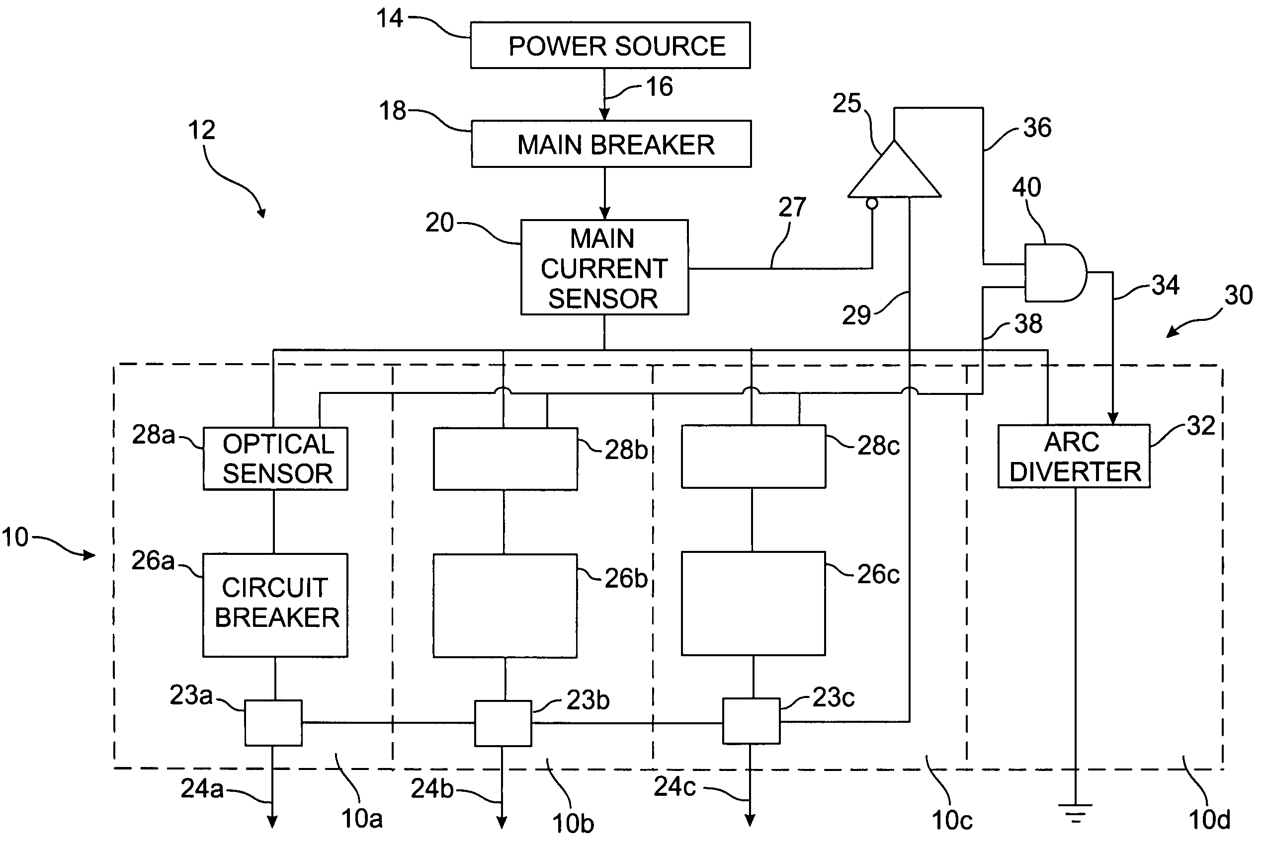
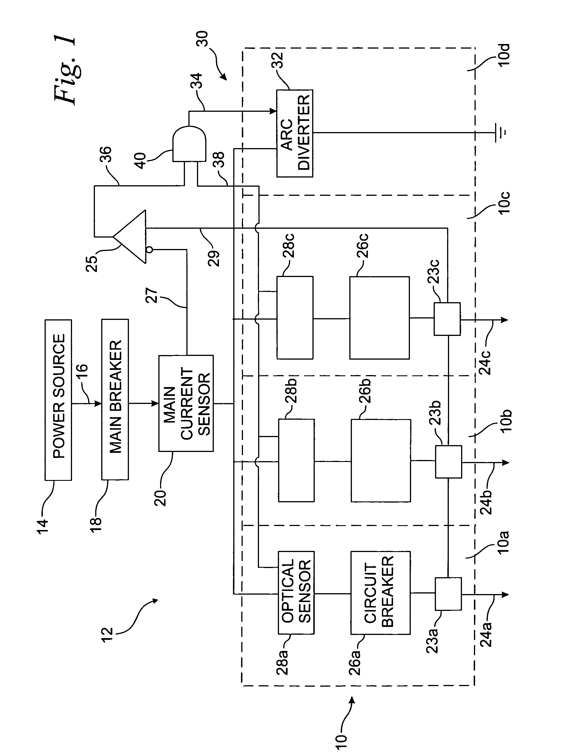
[0016]Turning now to the drawings and referring first to FIG. 1, there is shown a switchgear enclosure, generally designated by reference numeral 10, including individual compartments 10a, 10b, 10c and 10d, collectively 10, for housing various components of an electrical distribution system 12. A power source 14, which may comprise, for example, a utility company power transformer, supplies power for the distribution system 12 through a main circuit 16. The main circuit 16 is typically routed through a main breaker, designated here by reference numeral 18. A main current sensor 20 such as a toroidal coil may also be provided for monitoring the main circuit 16 for characteristics of arcing faults, as is known in the art. A source bus 22 connected to the main circuit 16 distributes electrical power from the power source 14 to a plurality of feeder circuits 24a, 24b, 24c, each of which is routed through one of the switchgear compartments 10. Each of the feeder circuits, collectively 24...


PUM


Abstract

An arcing fault protection system for a switchgear enclosure includes an arc diverter for rapidly grounding or crow-barring the electrical distribution system in response to the detection of arcing fault currents in the system. Detection is done through a comparison of current on the main bus against the current through the feeder lines, whereby a difference in current gives a first detection signal. The first detection signal can be used directly, or AND'ed with other detection signals from optical sensors on the feeder lines, to provide the activation signal for operating the arc diverter.

Description

BACKGROUND OF THE INVENTION[0001]1. Field of the Invention[0002]The present invention relates generally to protective devices for electrical switchgear and, more particularly, to the protection of electrical switchgear from arcing fault currents.[0003]2. Discussion of the Related Art[0004]Switchgear enclosures are commonly employed in electrical power distribution systems for enclosing circuit interrupters and switching equipment associated with the distribution system. Typically, switchgear enclosures are comprised of a number of individual stacked or adjacent compartments, each of the switchgear compartments receiving electrical power from a power source and distributing the electrical power through a feeder circuit to one or more loads. Generally, each of the switchgear compartments includes circuit interrupters for breaking electric power in a particular feeder circuit in response to hazardous current overloads in the circuit, or normal switching events.[0005]In addition to curr...

Claims


Application Information

Patent Timeline
Patent Type & Authority Patents(United States)
IPC IPC(8): H02H3/00H02H1/00
CPCH02H1/0015H02H1/0023
Inventor BYRON, ELDRIDGE R
Owner SQUARE D CO
Why Eureka
Try Eureka