Displacement sensor

a technology of displacement sensor and displacement electrode, which is applied in the direction of speed/acceleration/shock measurement device, resistance/reactance/impedence, test/calibration, etc., can solve the problem of difficult to precisely adjust the distance between the electrodes of the condenser, the distance is not constant, and the distance is difficult to precisely adjust the distance between the mass and the upper silicon sheet. achieve the effect of high yield and easy manufacturing

Inactive Publication Date: 2009-03-10
TOYOTA CENT RES & DEV LAB INC +1
View PDF11 Cites 10 Cited by
  • Summary
  • Abstract
  • Description
  • Claims
  • Application Information

AI Technical Summary

Benefits of technology

[0013]The present invention presents a new and novel configuration for a displacement sensor in which it is easy to adjust, to a determined value, the distance between electrodes of the condensers for measuring the degree of displacement.
[0062]According to the present invention, a condenser in which distance between electrodes has been adjusted to a constant value can be manufactured easily, and high yield manufacture is possible of a displacement sensor in which sensor characteristics have been adjusted to a constant value.

Problems solved by technology

It is difficult to precisely adjust the distance between the mass and the upper silicon sheet and the distance between the mass and the lower silicon sheet in the acceleration sensor of Japanese Laid Open Patent Application Publication H02 (1990)-134570.
That is, it is difficult to precisely adjust the distance between the electrodes of the condensers.
This may create the problem that the distance is not constant between the electrodes of the condensers consisting of the mass and the silicon sheets.
Furthermore, this issue is not limited to the case of differential sensors.

Method used


Image

  • Displacement sensor
  • Displacement sensor
  • Displacement sensor

Examples


first embodiment

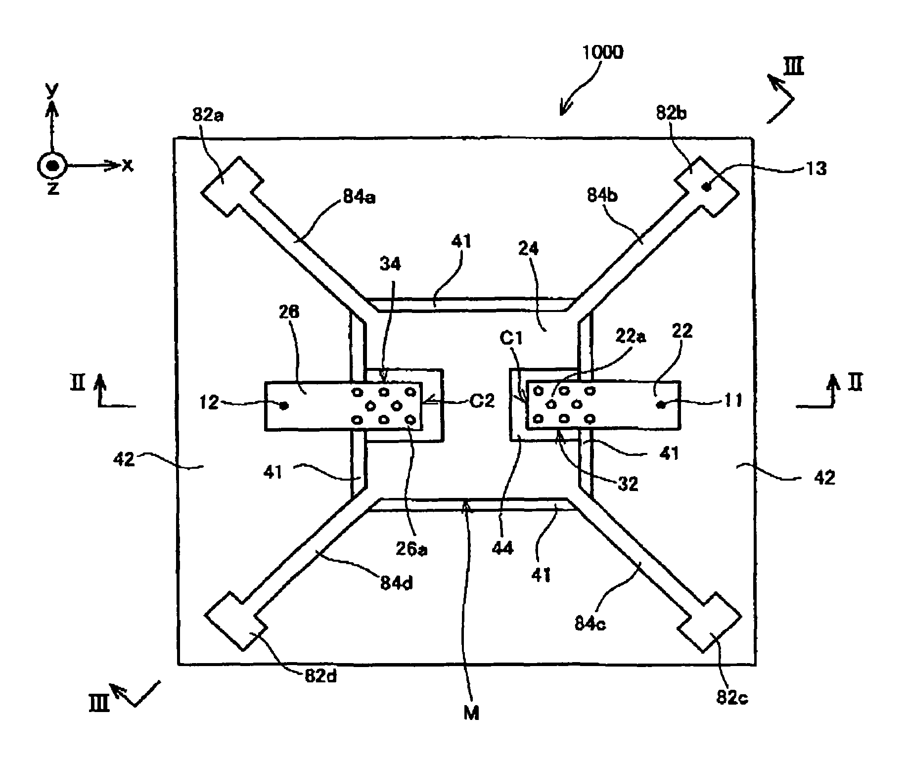
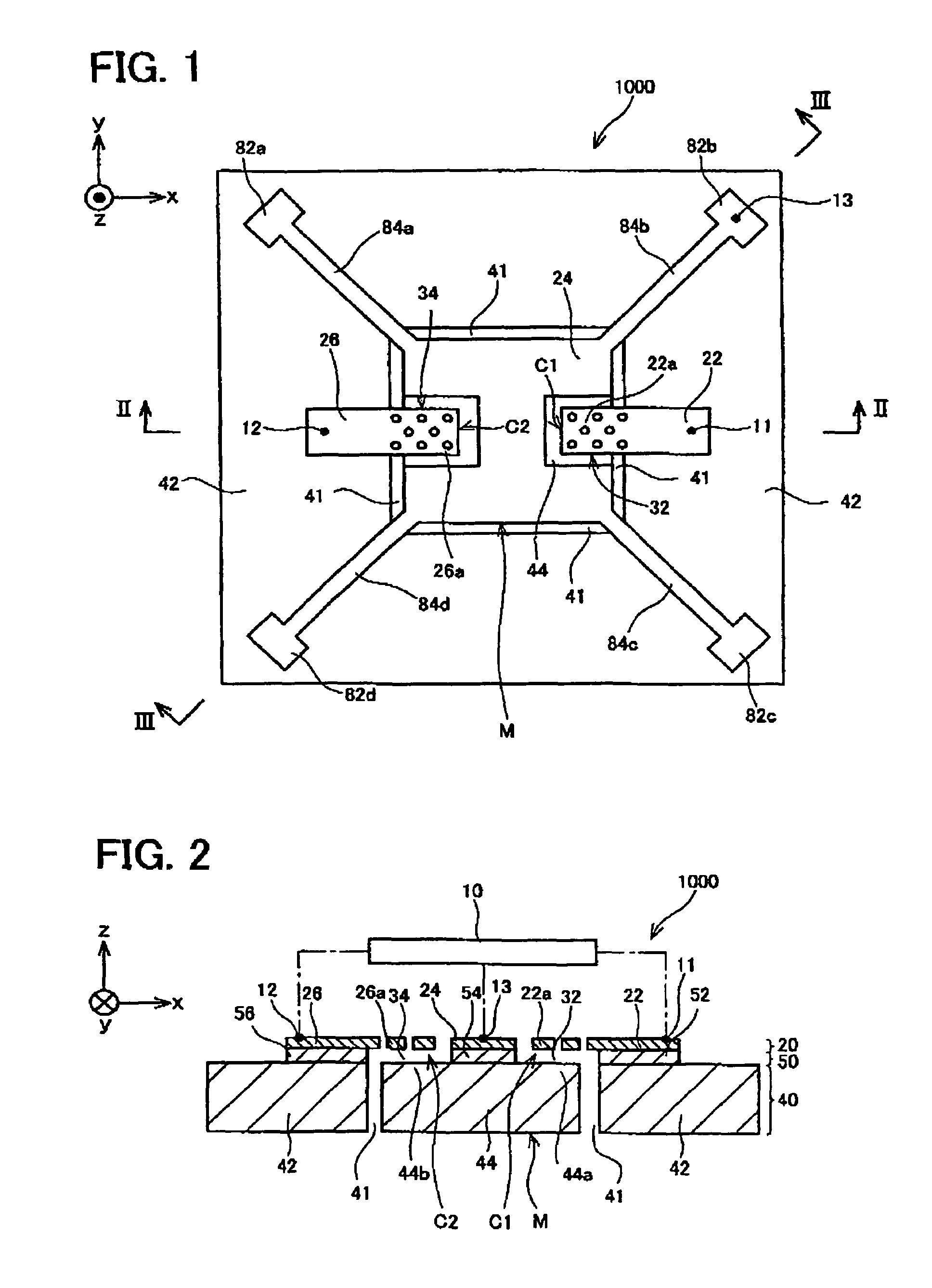
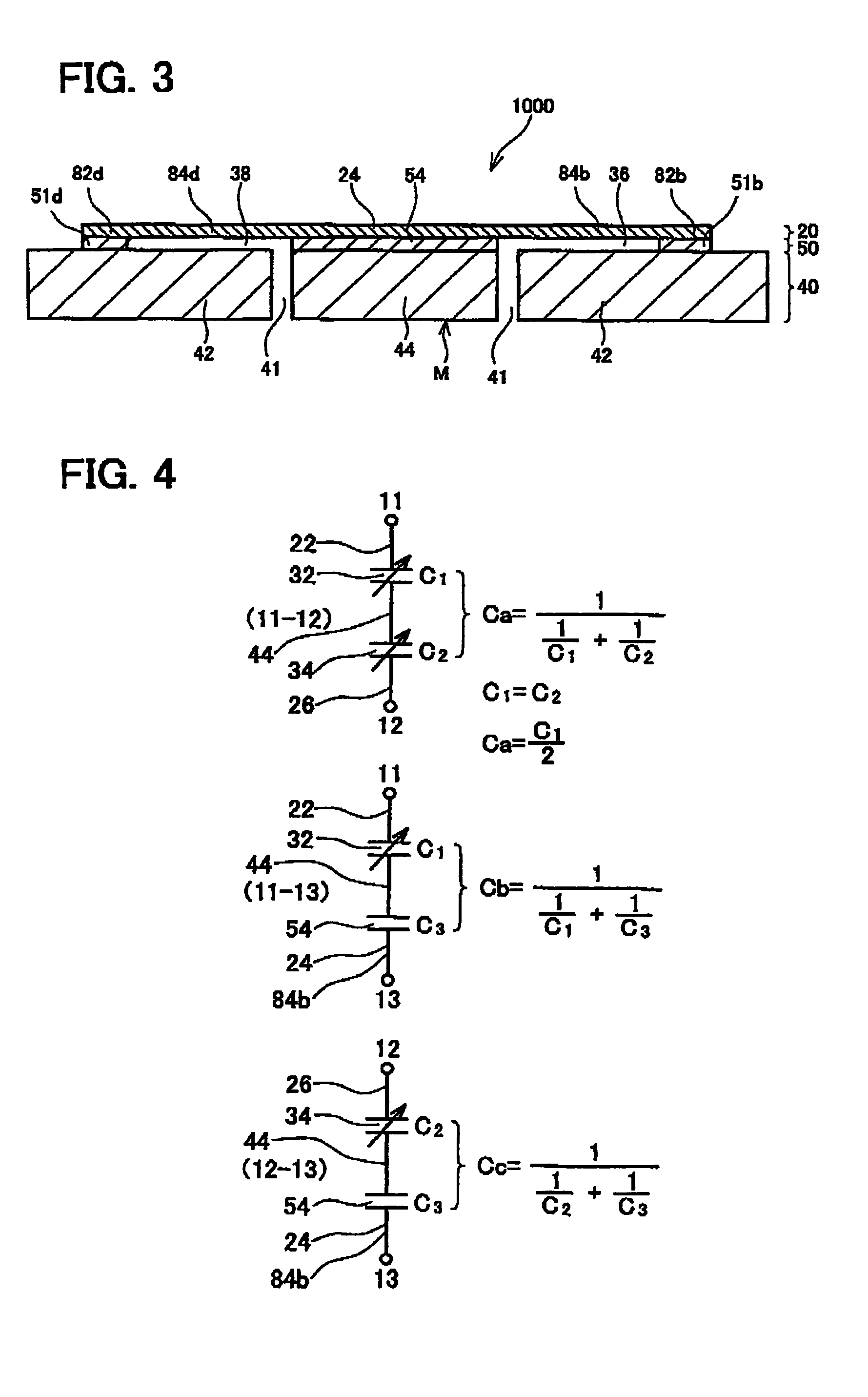
[0101]FIGS. 1 to 3 schematically show the structure of an acceleration sensor 1000. FIG. 1 is a plan view of the acceleration sensor 1000. FIG. 2 corresponds to a longitudinal section along a line II-II of FIG. 1, and FIG. 3 corresponds to a longitudinal section along a line III-III of FIG. 1. The acceleration sensor 1000 is used to measure acceleration in a z direction (a direction perpendicular to the face of the page in FIG. 1, and the up-down direction of the page in FIGS. 2 and 3).

[0102]First, a simple description will be given of the structure of the acceleration sensor 1000 with reference to FIGS. 1 to 3. The acceleration sensor 1000 is made of an SOI (Silicon on Insulator) having stacked layers comprising a conductive lower layer 40 formed from monocrystal silicon, an insulating layer 50 formed from silicon oxide stacked on the conductive lower layer 40, and a conductive upper layer 20 formed from monocrystal silicon stacked on the insulating layer 50. The insulating layer 5...

second embodiment

[0122]FIGS. 5 and 6 schematically show the structure of an acceleration sensor 1100 of a second embodiment. A description might be omitted of components configured identically to those of the first embodiment. The acceleration sensor 1100 performs detection by differentiating the degree of change in electrostatic capacity of a pair of condensers C1 and C4.

[0123]As shown in FIGS. 5 and 6, a conductive upper layer 20 of the acceleration sensor 1100 is provided with a first upper portion 22 forming one of electrodes of a condenser C1. The first upper portion 22 extends from a position above a first lower region 44 to a position above a second lower region 42. A first fixing insulating layer 52 is formed between the first upper portion 22 and the second lower region 42. An insulating layer 50 is not formed between the first lower region 44 and a first extending portion 22a of the first upper portion 22. A first condenser C1 is formed from the first extending portion 22a and a first oppo...

third embodiment

[0134]FIGS. 8 and 9 schematically show the structure of an acceleration sensor 1200 of a third embodiment. The acceleration sensor 1200 is a variant of the acceleration sensor 1100 of the second embodiment.

[0135]In the acceleration sensor 1200, as shown in FIGS. 8 and 9, a region that includes a second opposing portion 46a—this being opposite a second extending portion 24a of a second upper portion 24—(hereafter, this region will be termed a second opposing lower region 46) is insulated from a remaining portion of a second lower region 42. This insulation is attained by means of a slit 49 that penetrates a conductive lower layer 40. The slit 49 is connected with a dividing groove 41.

[0136]As shown in FIGS. 8 and 9, the second opposing lower region 46 is fixed to the second lower region 42 via a portion 53 of an insulating layer 50. Although the second opposing lower region 46 is electrically separated from the second lower region 42 by the slit 49, it is mechanically fixed thereto v...


PUM


Abstract

A structure is presented in which it is easy to adjust, to a determined value, distance between electrodes of a condenser formed in an electrostatic capacity-type displacement sensor.A displacement sensor has a conductive lower layer, an insulating layer stacked on the conductive lower layer and a conductive upper layer stacked on the insulating layer. The conductive lower layer is divided into a first lower region and a second lower region by a groove penetrating the conductive lower layer. The insulating layer is stacked on the conductive lower layer at selected portions. The conductive upper layer is stacked on the insulating layer at selected portions. The conductive upper layer has a beam connected via the insulating layer to the first lower region and the second lower region at a pair of ends of the beam. The conductive upper layer has a first upper portion forming one of electrodes of a first condenser. The first upper portion extends from a position above the first lower region to a position above the second lower region. The insulating layer is not formed between the first upper portion and the first lower region, but is formed between the first upper portion and the second lower region.

Description

CROSS-REFERENCE TO RELATED APPLICATION[0001]The present application claims priority based on Japanese Patent application 2004-067555 filed on Mar. 10, 2004, the contents of which are hereby incorporated by reference within this application.BACKGROUND OF THE INVENTION[0002]1. Field of the Invention[0003]The present invention relates to a displacement sensor for detecting the degree of displacement of an object that is subjected to force and thus displaced. If the degree of displacement of the object is detected, it is possible to measure the force applied to the object, or to measure the acceleration, angular acceleration, pressure, external force, etc. that created this force. The displacement sensor referred to here is a sensor that, by measuring physical value that changes depending on the degree of displacement, is capable of directly detecting the degree of displacement, and of indirectly measuring acceleration, angular acceleration, pressure, external force, etc.[0004]In the pr...

Claims


Application Information

Patent Timeline
Patent Type & Authority Patents(United States)
IPC IPC(8): G01R27/26G01P15/125G01B3/30G01B21/00G01P15/08G01P21/00
CPCG01P15/0802G01P15/125
Inventor FUJIYOSHI, MOTOHIRONONOMURA, YUTAKASUGIHARA, HISAYOSHI
Owner TOYOTA CENT RES & DEV LAB INC
Why Eureka
Try Eureka