Forming a tubular knit fabric for a paint roller cover

a technology of knitted fabric and paint roller cover, which is applied in the direction of knitting, textiles and papermaking, weft knitting, etc., can solve the problems of increasing the cost of manufacturing a roller cover, leaving visible marks on the surface being painted or otherwise coated, etc., and achieves the effect of enhancing durability and robustness

Active Publication Date: 2009-03-17
SEAMLESS TECH
View PDF57 Cites 22 Cited by
  • Summary
  • Abstract
  • Description
  • Claims
  • Application Information

AI Technical Summary

Benefits of technology

[0011]In some forms of the invention, where the pile yarn is a sliver fiber, the pile yarn feeding arrangement includes a doffer arrangement having a doffer wheel including a sliver feeding surface thereof which is operatively disposed adjacent to a sliver-feed segment of the periphery of the dial, in such a manner that the hooked ends of the dial needles are adapted to receive sliver fiber from the sliver feeding surface of the doffer wheel during operation of the knitting apparatus. The dial needles may be configured to be moveable radially to a tuck position in which the hooks of the dial needles are extended beyond the periphery of the dial, but the previous loop of the backing is not cast off, and the sliver feeding surface is disposed such that the hooks of the dial needles can receive the sliver fiber from the sliver feeding surface while the dial needles are in the tuck position. Because the dial needles need to move radially outward only to the tucked position, rather than a fully extended position, they are better supported within the dial needle slots than they would be in a fully extended position, thereby providing enhanced durability and robustness to the dial knitting arrangement, according to the invention.

Problems solved by technology

The use of helically wound strips to provide the pile on roller covers is undesirable because, even where great care is taken in precisely cutting and winding the strips of fabric onto the core, the resulting juncture between two adjacent strips still sometimes results in noticeable marks being left on the surface being painted or otherwise coated by the roller cover.
The precise cutting and winding operations required to produce a roller cover giving satisfactory performance can substantially increase the cost of manufacturing a roller cover.
For the most popular type of knitted fabric for roller covers, having a pile formed from small tufts, known as slivers, of fabric knitted into a knitted backing, another drawback existed in prior methods and apparatuses which were only capable of producing tubular-shaped knitted coverings having the pile extending from an inner surface of the tubular-shaped length of knitted covering.

Method used


Image

  • Forming a tubular knit fabric for a paint roller cover
  • Forming a tubular knit fabric for a paint roller cover
  • Forming a tubular knit fabric for a paint roller cover

Examples


Embodiment Construction

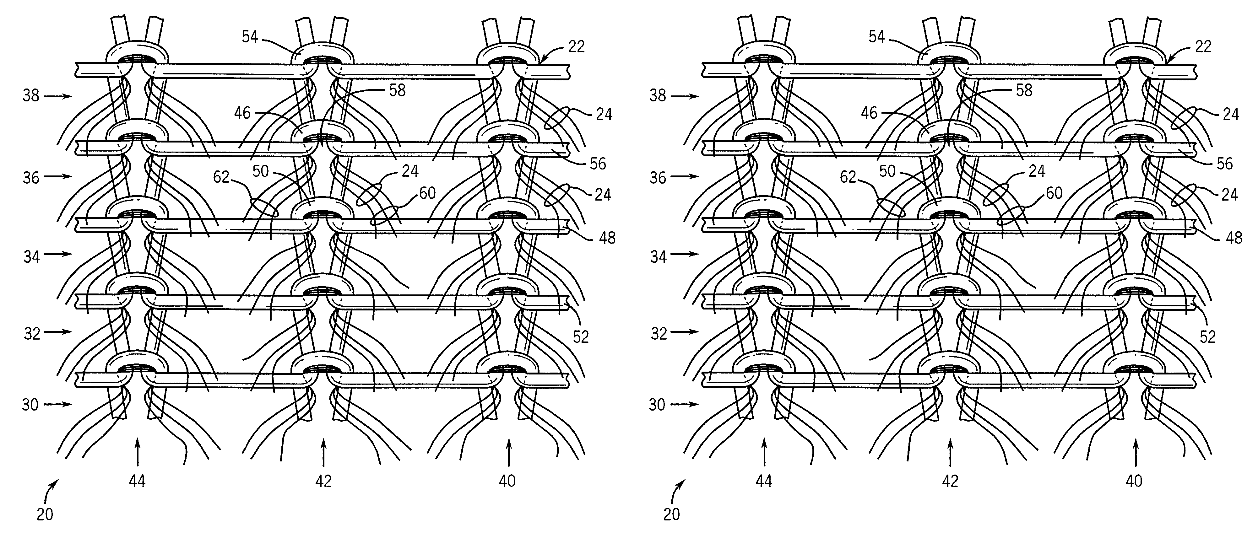
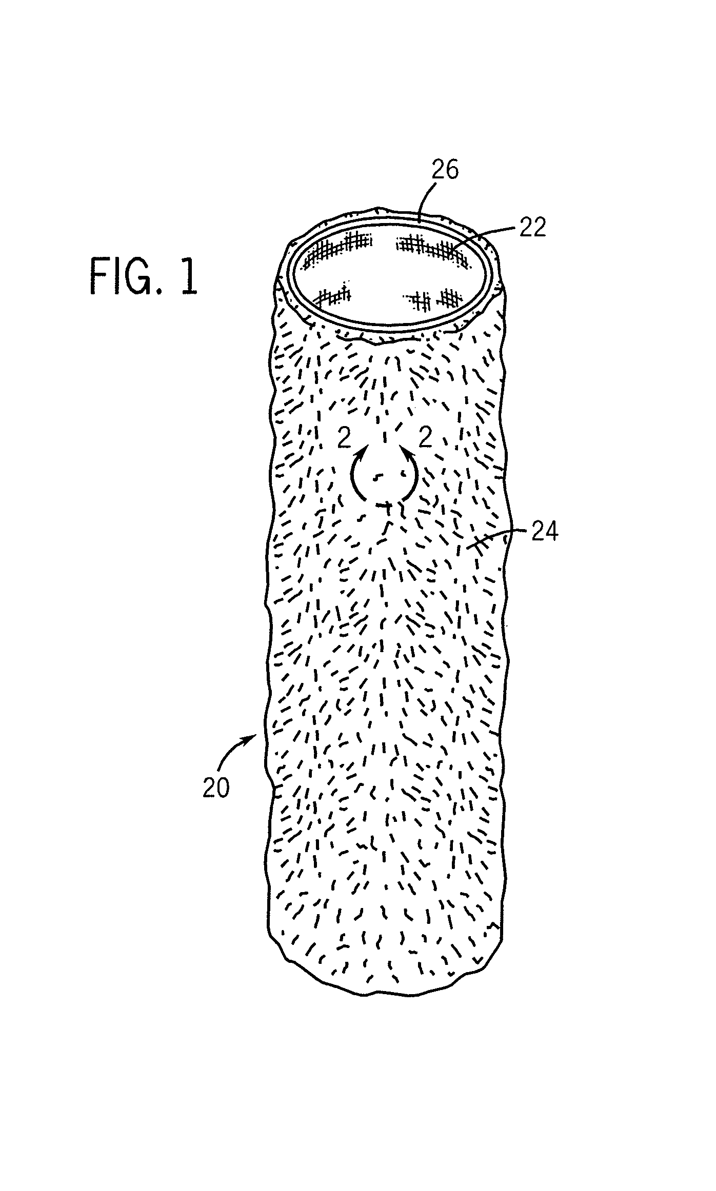
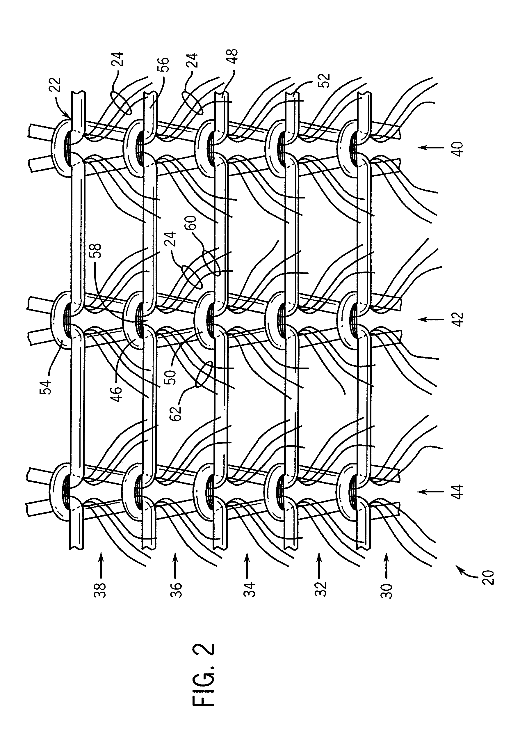
[0048]FIG. 1 shows a first exemplary embodiment of a tubular-shaped sliver-knitted covering 20 for a paint roller having pile fibers 24 extending from a lightweight knit backing or base material 22, that is knitted according to a method illustrated in FIGS. 2 through 9, on a first embodiment of a knitting apparatus 100 shown in FIGS. 10 through 13. As will be readily understood by those having skill in the art, the tubular sliver knit segment 20 may be readily pulled over and affixed to a core (not shown) to form a completed roller cover according to one of the methods shown in the inventor's commonly assigned U.S. patent application Ser. No. 11 / 740,119 or another appropriate manner, without the necessity for resorting to helically wrapping a strip of sliver-knitted fabric about the core as was required in prior roller covers.

[0049]A tubular sliver knit segment 20 of the type shown in FIG. 1 may be continuously knitted in an extended length using the exemplary embodiment of the inve...


PUM


Abstract

A method and apparatus are provided for forming a tubular-shaped knitted covering for a paint roller, or the like, having a pile extending from an outer surface of the covering, through use of a dial needle knitting arrangement. A cylinder needle knitting arrangement may be utilized in conjunction with the dial needle knitting arrangement for forming a tubular-shaped knitted covering for a paint roller having a pile formed from a combination of sliver and yarn fibers in successive courses of the tubular-shaped knitted covering.

Description

FIELD OF THE INVENTION[0001]This invention relates generally to the manufacture of knitted fabric having a pile extending from a surface thereof, and more particularly to the manufacture of a tubular-shaped knitted fabric having a pile extending from an outer surface thereof in small diameters suitable for use as a covering for a paint roller.BACKGROUND OF THE INVENTION[0002]Since the 1930s, rollers have been utilized for applying paint and other coatings to walls, ceilings, floors, and other surfaces. Typically, a roller includes two components, in the form of a handle assembly and a roller cover for installation onto the handle assembly. The handle assembly typically consists of a grip element having a generally L-shaped metal frame extending therefrom, with the free end of the metal frame having a rotatable support for the roller cover to be mounted thereon. The roller cover typically consists of a thin, hollow cylindrical core which fits onto the rotatable support of the handle,...

Claims


Application Information

Patent Timeline
Patent Type & Authority Patents(United States)
IPC IPC(8): D04B9/12
CPCD04B9/14D04B15/14D04B15/18D04B15/80D04B1/025D04B9/12
Inventor KNIGHT, SR., JOHN CECILSINYKIN, DANIEL L.
Owner SEAMLESS TECH
Why Eureka
Try Eureka