Control system for multiphase rotary electric machines

a control system and multi-phase technology, applied in the direction of electronic commutators, motor/generator/converter stoppers, dynamo-electric converter control, etc., can solve the problem of at least one occupant being subjected to a shock (torque shock), and achieve the effect of preventing torque shock

Active Publication Date: 2009-03-17
DENSO CORP
View PDF4 Cites 33 Cited by
  • Summary
  • Abstract
  • Description
  • Claims
  • Application Information

AI Technical Summary

Benefits of technology

[0009]Accordingly, an object of at least one aspect of the present invention is to prevent torque shock from occurring due to an intermittent change of an output torque of a multiphase rotary electric machine.

Problems solved by technology

When the multiphase rotary electric machine is installed in a vehicle, such as a hybrid vehicle, the sudden change of the output torque of the machine may cause at least one occupant to be subjected to a shock (torque shock).

Method used


Image

  • Control system for multiphase rotary electric machines
  • Control system for multiphase rotary electric machines
  • Control system for multiphase rotary electric machines

Examples


Embodiment Construction

[0022]An embodiment of the present invention will be described hereinafter with reference to the accompanying drawings. In the embodiment, the present invention is, for example, applied to a control system for a three-phase rotary electric machine installed in a hybrid vehicle; this three-phase motor-generator is an example of various types of multiphase rotary electric machines.

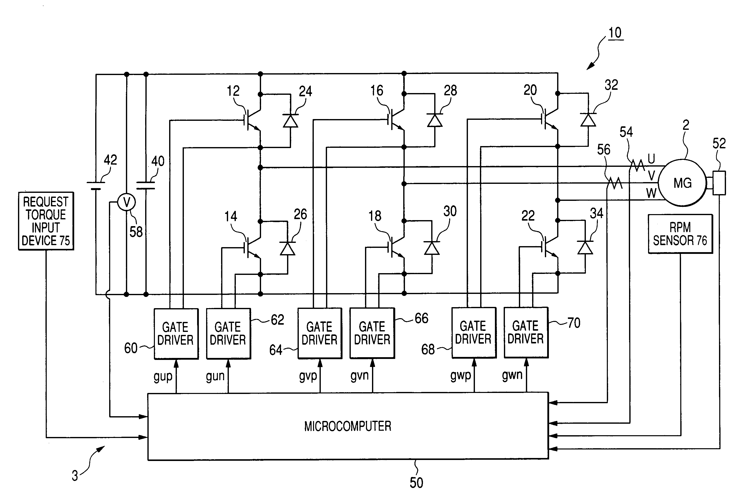
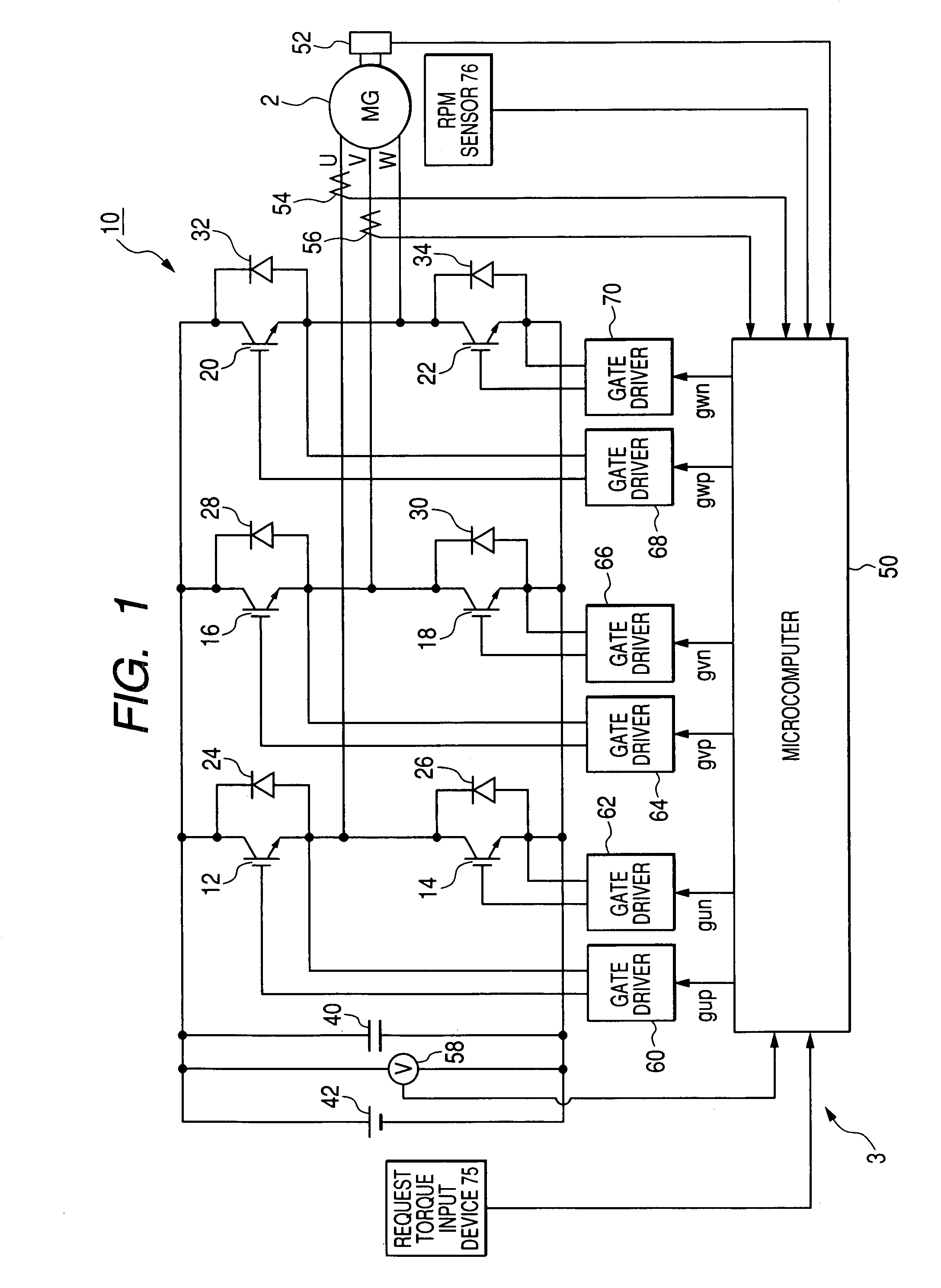
[0023]Referring to the drawings, in which like reference characters refer to like parts in several figures, particularly to FIG. 1, there is illustrated a three-phase motor-generator, referred to simply as “motor-generator (MG)”2 and a control system 3 for controlling the motor-generator 2.

[0024]For example, the motor-generator 2 is provided with an annular rotor whose rotor core is fixedly fitted around the outer periphery of a crankshaft of an engine installed in the hybrid vehicle. The rotor includes a rotor core. The rotor core is fixedly fitted around the outer periphery of a rotating shaft.

[0025]The ro...


PUM


Abstract

In a control system, a storing unit has stored a relationship between a workload associated with rotation of a multiphase rotary electric machine and a voltage utilization factor of the multiphase rotary electric machine. The voltage utilization factor includes information representing how percentage the direct current voltage applied to a switching element is used by the multiphase rotary electric machine. A measuring unit measures change in the workload associated with rotation of the multiphase rotary electric machine. A pulse control unit carries out a single pulse control to change an on duration of the switching element to be substantially equivalent to a half cycle of a cyclic current while continuously changing the voltage utilization factor based on the relationship stored in the storing unit and the measured change of the workload.

Description

CROSS REFERENCE TO RELATED APPLICATIONS[0001]This application is based on Japanese Patent Application 2006-101325 filed on Apr. 3, 2006. This application claims the benefit of priority from the Japanese Patent Application, so that the descriptions of which are all incorporated herein by reference.FIELD OF THE INVENTION[0002]The present invention relates to control systems for multiphase rotary electric machines, which are capable of smoothly switching a current control mode of an inverter to a single pulse mode.BACKGROUND OF THE INVENTION[0003]An example of various types of control units for a multiphase rotary electric machine is configured to carry out PWM (Pulse Width Modulation) control. Specifically, during the PWM control, the control unit compares a request current wave required to output a request torque with a carrier triangle wave, and generates a plurality of voltage pulses in every cycle of the request current wave based on the comparison result. These voltage pulses all...

Claims


Application Information

Patent Timeline
Patent Type & Authority Patents(United States)
IPC IPC(8): H02P7/00H02P6/06H02P6/08H02P6/17H02P6/28
CPCH02P21/0089H02P21/06
Inventor TSUJI, HIROYAYAMADA, TAKAHIROKIMURA, TOMONORI
Owner DENSO CORP
Why Eureka
Try Eureka