Device and method for forming small-diameter flanging holes in aluminum alloy plate through magnetic pulses

An aluminum alloy plate and magnetic pulse forming technology, applied in the field of plastic forming and manufacturing of metal plate parts, can solve the problems of difficulty in obtaining parts that meet flanging holes, easy damage to the processed parts, unstable forming quality, etc. It can convert into mechanical energy with high efficiency, solve the effect of low coil life, and solve the effect of many process passes

Active Publication Date: 2014-06-18
HARBIN INST OF TECH
View PDF6 Cites 35 Cited by
  • Summary
  • Abstract
  • Description
  • Claims
  • Application Information

AI Technical Summary

Problems solved by technology

[0004] The purpose of the present invention is to provide a magnetic pulse forming device and method for small-diameter flanging holes in aluminum alloy sheets, so as to solve the problem of low coil life and low workpiece It is easy to

Method used


Image

  • Device and method for forming small-diameter flanging holes in aluminum alloy plate through magnetic pulses
  • Device and method for forming small-diameter flanging holes in aluminum alloy plate through magnetic pulses
  • Device and method for forming small-diameter flanging holes in aluminum alloy plate through magnetic pulses

Examples


specific Embodiment approach 1

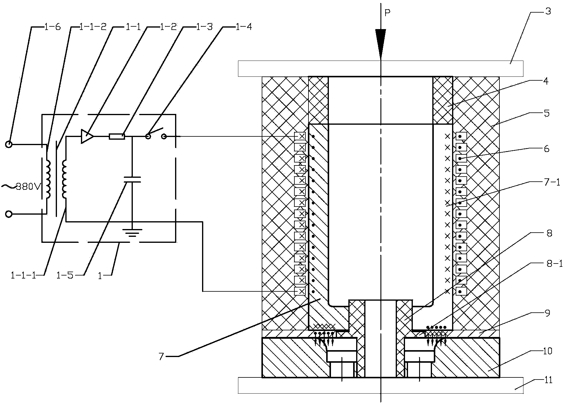
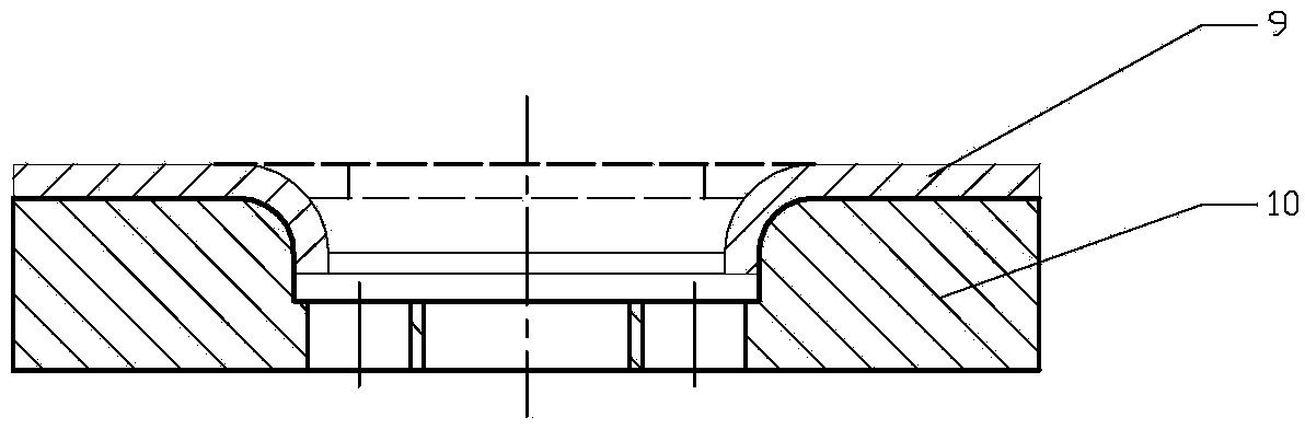
[0014] Specific implementation mode one: as Figure 1 ~ Figure 3 As shown, a magnetic pulse forming device for a small-diameter flanging hole in an aluminum alloy plate according to this embodiment includes a magnetic pulse control circuit 1, an upper platen 3, a magnetic collector limit ring 4, a columnar magnetic collector 7, and a positioning ring 8 , flanging die 10, base plate 11 and solenoid coil; the solenoid coil includes a bobbin 5 and a coil turn 6, and the coil turn 6 is wound into a spiral cylindrical potting in the bobbin 5, and the flanging The die 10 is fixed on the upper end surface of the base plate 11, and the outer wall of the positioning ring 8 is provided with an annular platform 8-1. The annular platform 8-1 divides the positioning ring 8 into upper and lower sections. Inside, the upper part of the positioning ring 8 is set in the columnar magnetic collector 7, the magnetic collector limit ring 4 is arranged on the upper end surface of the columnar magnet...

specific Embodiment approach 2

[0016] Specific implementation mode two: combination figure 1 Note that the magnetic pulse control circuit 1 in this embodiment includes a high-voltage transformer 1-1, a rectifier 1-2, a current limiting resistor 1-3, a high-voltage switch 1-4, a capacitor bank 1-5, and an AC power supply 1-6; One end of the secondary coil 1-1-1 of the high voltage transformer 1-1 is connected to the anode of the rectifier 1-2, the cathode of the rectifier 1-2 is connected to one end of the current limiting resistor 1-3, and the current limiting resistor 1 The other end of -3 is connected with the positive pole of capacitor bank 1-5 and the positive pole of high-voltage switch 1-4, and the negative pole of high-voltage switch 1-4 is as described one output end of magnetic pulse control circuit 1, and the secondary of high-voltage transformer 1-1 The other end of the primary coil 1-1-1 is connected to the power supply ground and the negative pole of the capacitor bank 1-5 and is used as the ot...

specific Embodiment approach 3

[0017] Specific implementation mode three: combination figure 1 Note that the width of the longitudinal slit 7-1 in this embodiment is 0.3-1mm. This narrow slit is used to cut off the induced current to form a loop directly on the surface of the outer wall of the magnet collector, so that the magnetic field in the gap between the inner surface of the coil and the outer wall of the magnet collector can be transmitted to the working area of ​​the magnet collector and the gap between the aluminum alloy plate. If the gap is too small, it is difficult to implement gap insulation treatment. On the contrary, the loss of magnetic field energy in the gap will increase, and the amplitude of the magnetic field force will be reduced, which is not conducive to the effect of flanging. The undisclosed technical features in this embodiment are the same as those in the second embodiment.


PUM

PropertyMeasurementUnit
Seam widthaaaaaaaaaa

Abstract

The invention discloses a device and method for forming small-diameter flanging holes in an aluminum alloy plate through magnetic pulses, and belongs to the field of metal plate part plastic forming and manufacture. The device and method solve the problems that when the flanging holes are formed in the aluminum alloy plate through an existing magnetic pulse forming technology, the service life of a coil is short, damage easily happens to the machined workpiece, a plurality of flanging and forming procedures exist when a steel die is adopted, and the forming quality is not stable. A coil wire turn is packaged in a coil framework, a flanging female die is fixed to a bottom plate, the upper section of a positioning ring and the lower section of the positioning ring are arranged in a columnar magnetic trap and the flanging female die, a magnetic trap limiting ring is arranged on the upper end face of the columnar magnetic trap, the solenoid coil is arranged on the outer side wall of the columnar magnetic trap and the outer side wall of the magnetic trap limiting ring in a sleeved mode, and a longitudinal seam is formed in the side wall of the columnar magnetic trap. An upper pressing plate is arranged on the upper end face of the magnetic trap limiting ring and the upper end face of the coil framework. The aluminum alloy plate is arranged between the flanging female die and the coil framework, and two output ends of a magnetic pulse control circuit are connected with two wiring terminals of the coil wire turn. The device and method are used for forming the small-diameter flanging holes in the aluminum alloy plate through magnetic pulses.

Description

technical field [0001] The invention relates to a magnetic pulse forming device and method for small-diameter flanging holes of metal plates, belonging to the field of plastic forming and manufacturing of metal plate parts. Background technique [0002] In order to improve the atmospheric environment, energy saving and consumption reduction are the principles that must be followed for the sustainable development of the manufacturing industry, and the lightweight of structures and materials is an inevitable way. Due to the characteristics of high specific strength, in the advanced automobile manufacturing industry, light alloy plates such as high-strength aluminum alloys and magnesium alloys are used more and more, and in the aerospace manufacturing industry, aluminum alloys are widely used in various Launch vehicle and aircraft. In the frame structure commonly used in aerospace vehicles, there are many positions where holes need to be flanged. On the one hand, the structura...

Claims


Application Information

Patent Timeline
IPC IPC(8): B21D26/14
Inventor 于海平陈杰范志松李春峰
Owner HARBIN INST OF TECH
Why Eureka
Try Eureka