Large-load pressure and pulling force sensor

A tension sensor and large load technology, applied in the field of sensing systems, can solve the problems of integrated tension and pressure sensors, the deviation of the tension and pressure measurement range, and limit the application of piezoelectric sensors, etc., to achieve small structure size, large detection force range, The effect of simple and convenient installation

Active Publication Date: 2013-07-17
杨锦堂
View PDF5 Cites 0 Cited by
  • Summary
  • Abstract
  • Description
  • Claims
  • Application Information

AI Technical Summary

Problems solved by technology

However, since piezoelectric materials are brittle materials with low compressive and tensile strengths, piezoelectric sensors made of them often cannot withstand large loads.
For example, a piezoelectric sensor currently on the market: CZ-YB series piezoelectric pressure sensor, its load capacity can only be tens of kilopascals, so the defect of the piezoelectric material’s own strength limits the application of piezoelectric sensors
Moreover, due to the different tensile and piezoelectric properties of piezoelectric materials, the pressure and tension integrated sensor made of a single piezoelectric material has the defects of inconsistent sensing signals and large deviations in the measurement range of tension and pressure. Difficulty with the pressure sensor

Method used


Image

  • Large-load pressure and pulling force sensor
  • Large-load pressure and pulling force sensor
  • Large-load pressure and pulling force sensor

Examples


Embodiment 1

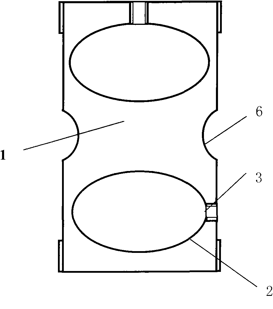
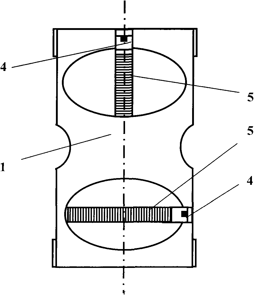
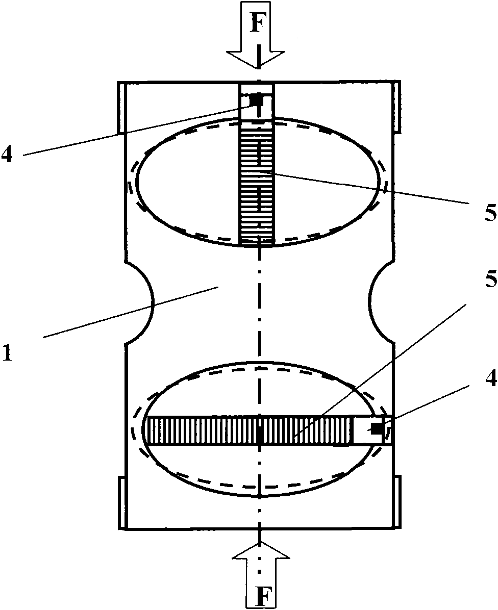
[0030] like figure 1 , figure 2 , image 3 , Figure 4 As shown, the sensor of the present invention includes an elastic frame 1, two cavities 2 are provided at the upper and lower ends of the elastic frame 1, and a through hole 3 is provided on the side of the cavity 2, and the fastener 4 arranged on the elastic frame runs through port 3; the cavity 2 is provided with a piezoelectric body 5, one end of the piezoelectric body 5 is fixedly connected to the fastener 4, and the other end is in contact with the inner wall of the cavity opposite to the through hole, and the piezoelectric body 5 is a force-electric transmission Sensitive material body.

[0031] The cavity 2 is a closed ellipsoid, and each cavity 2 is provided with a through opening 3. The upper hole 2 is provided with a through opening 3 at the upper end, and the lower hole 2 is provided with a through opening 3 at the right end, that is, the upper and lower ends of the piezoelectric The body is arranged vertic...

Embodiment 2

[0038] like Figure 5 As shown, only one cavity 2 is provided on the upper end of the elastic frame 1, and the upper end of the cavity 2 is provided with a through opening 3. Others are with embodiment 1.

Embodiment 3

[0040] like Image 6 As shown, only one cavity 2 is provided at the lower end of the elastic frame 1, and a through opening 3 is provided at the left end of the cavity 2. Others are with embodiment 1.


PUM


Abstract

The invention relates to a sensing system based on force strain materials, especially to an integrated sensor system that is capable of simultaneously carrying out pressure and pulling force detection under a large-load working environment. The large-load pressure and pulling force transducer includes an elastic frame; cavities are arranged on the elastic frame; penetrating openings are arranged at side surfaces of the cavities; and fasteners that are arranged on the elastic frame penetrate the penetrating openings. Piezoelectrics are arranged in the cavities; one ends of the piezoelectrics are fixedly connected with the fasteners; and the other ends of the piezoelectrics are contacted with inner walls in the cavities, wherein the inner walls of the cavities are opposite to the penetrating openings. According to the invention, the sensor can be applied to fields requiring to test a large load or a super large load, wherein the fields relates to pulling force and pressure detection fields of a building, a heavy machine, a bridge and hydraulic equipment and the like. According to the sensing system, it can be avoided that a sensor that is manufactured by a piezoelectric material cannot be applied to application occasions of detection on a large load force or a super large load force due to restrictions of compressive strength and tensile strength of the piezoelectric material itself.

Description

technical field [0001] The invention relates to a sensor system based on a force-strain material, in particular to an integrated sensor system capable of simultaneously detecting pressure and tension in a large-load working environment. Background technique [0002] The field of sensors has developed rapidly, resulting in a variety of sensors such as pressure change, piezoresistive and piezoelectric. Especially in recent years, piezoelectric sensors have developed rapidly. The principle of the piezoelectric sensor is based on the piezoelectric effect of some crystal materials. The widely used piezoelectric materials are quartz and lead pertitanate. When these crystals are mechanically deformed by pressure, the two opposite sides Opposite charges are generated on the sides, which is the "piezoelectric effect". Since the piezoelectric sensor is made based on the force-electric strong coupling effect of this piezoelectric material, the intensity of the mechanical load is sens...

Claims


Application Information

Patent Timeline
Patent Type & Authority Patents(China)
IPC IPC(8): G01L1/00G01L1/16G01L1/26
Inventor 杨锦堂李健
Owner 杨锦堂
Why Eureka
Try Eureka