
Wiper controller and method for controlling wiper

a technology of wiper controller and wiper, which is applied in the direction of mechanical control devices, vehicle cleaning, instruments, etc., can solve the problems of inability to control the intermittent wipe cycle, the wipe cycle may not be properly adjusted, and the correction must be performed

Active Publication Date: 2009-03-17
KK TOKAI RIKA DENKI SEISAKUSHO
View PDF12 Cites 59 Cited by
  • Summary
  • Abstract
  • Description
  • Claims
  • Application Information

AI Technical Summary

Benefits of technology

[0006]The present invention provides a wiper controller for automatically correcting resistance value variations in an intermittent wipe cycle setting device.

Problems solved by technology

Thus, when using the resistance value of the resistor circuit to control the intermittent wipe cycle, the wipe cycle may not be properly adjusted.
Thus, the intermittent wipe cycle may not be controlled in accordance with the position of the cycle setting device.
However, due to the variance between different cycle setting devices, the correction must be performed for each cycle setting device.
Such processing is burdensome.

Method used


Image

  • Wiper controller and method for controlling wiper
  • Wiper controller and method for controlling wiper
  • Wiper controller and method for controlling wiper

Examples


Embodiment Construction

[0015]A wiper controller according to a preferred embodiment of the present invention will now be described with reference to the drawings.

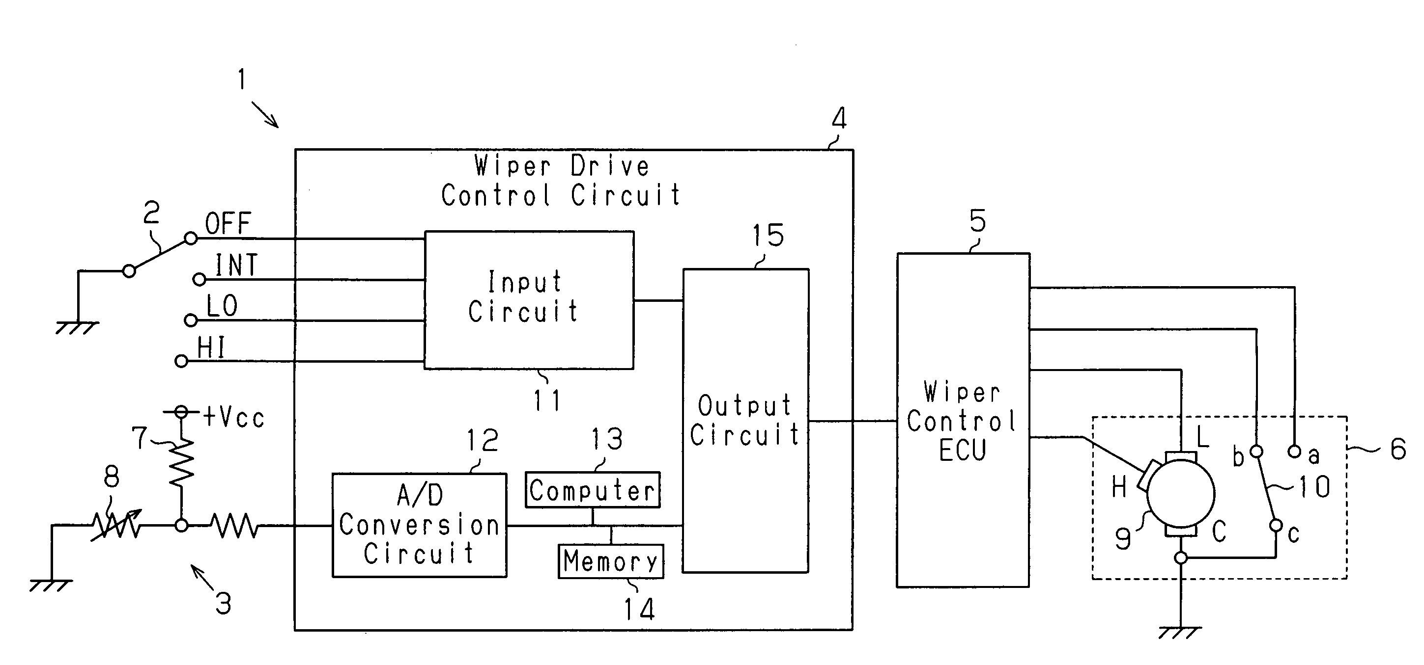
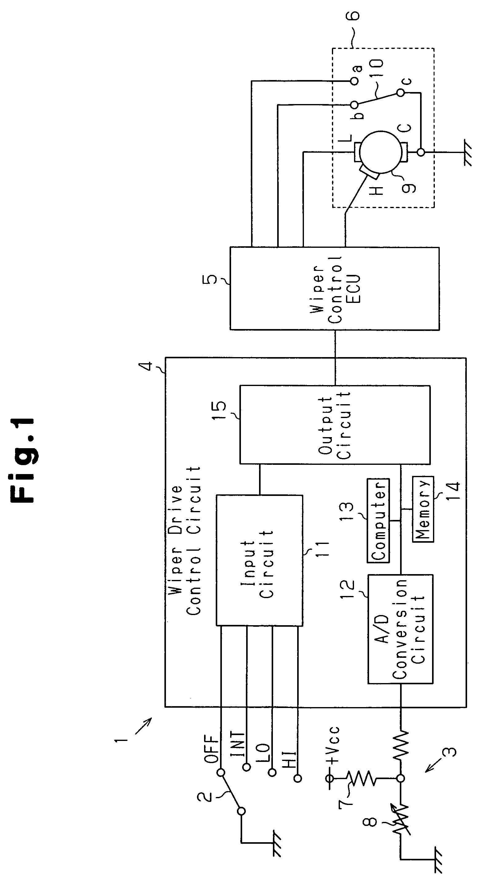
[0016]As shown in FIG. 1, a wiper unit 1 includes a wiper switch 2, an intermittent wipe cycle setting device 3 (volume), a wiper drive control circuit 4 connected to the wiper switch 2 and the cycle setting device 3, a wiper control ECU 5 connected to the wiper drive control circuit 4, and a wiper driver 6 connected to the wiper control ECU 5. In the preferred embodiment, the wiper control ECU 5 and the wiper driver 6 form a wiper drive unit.

[0017]The wiper switch 2 is switched between a plurality of positions in accordance with the operation of a wiper lever (not shown), which is arranged in, for example, the passenger compartment. In the preferred embodiment, the wiper switch 2 is switched between an off position “OFF”, an intermittent wipe mode position “INT”, a low speed wipe mode position “LO”, and a high speed wipe mode position “HI”. The ...


PUM


Abstract

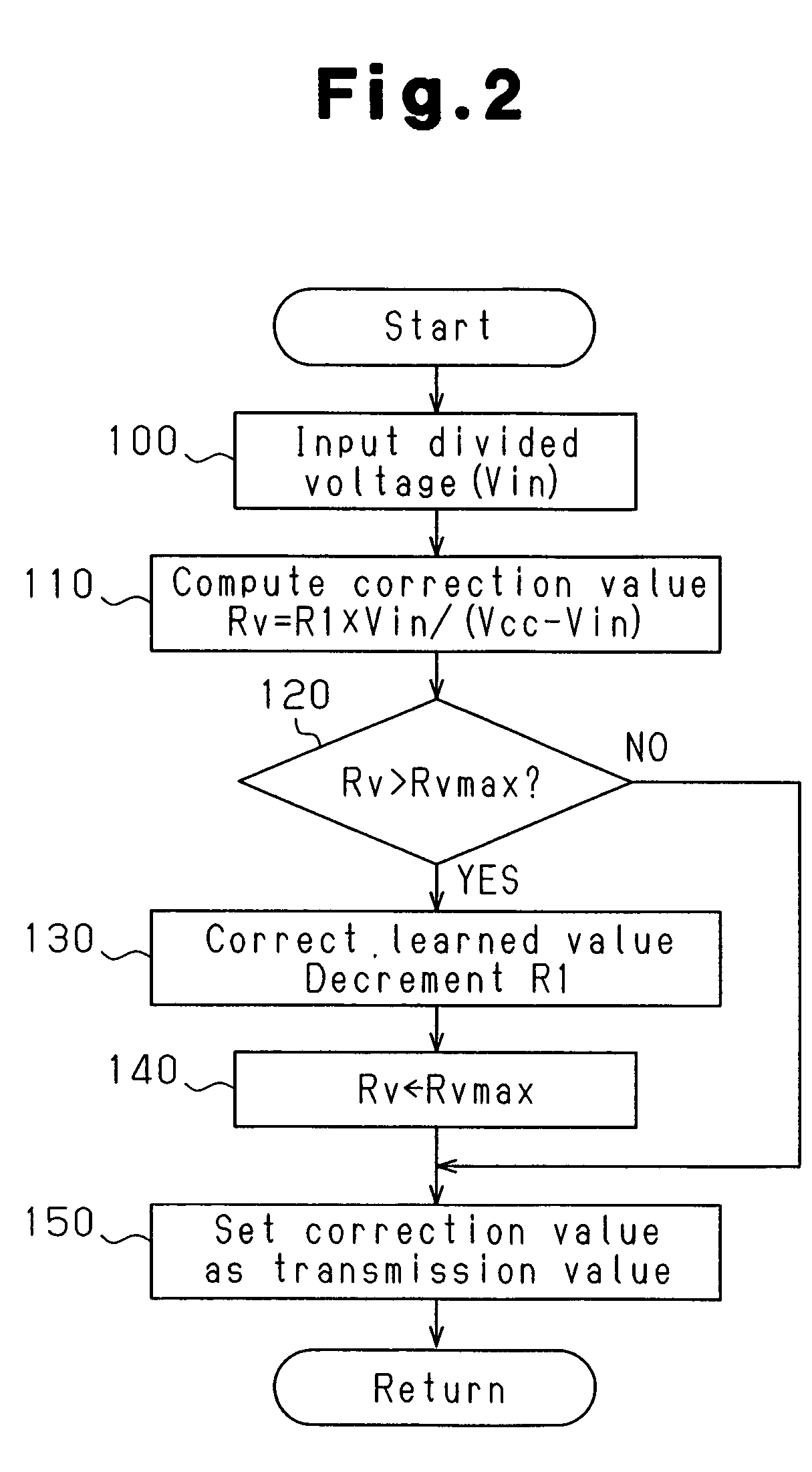
A controller for controlling a wiper unit including a wiper and an intermittent wipe cycle setting device for setting an intermittent wipe cycle of the wiper. The cycle setting device is set at a plurality of positions respectively corresponding to different intermittent wipe cycles. Further, the cycle setting device has a resistance value, which changes in accordance with each of the positions, and generates an output signal, which is in accordance with the change in the resistance value. The controller computes position information of the intermittent wipe cycle setting device from the output signal by using a learned value. The computer adjusts the learned value in accordance with the computation result of the position information to correct the position information. Accordingly, resistance value variances of the intermittent wipe cycle setting device are automatically corrected.

Description

BACKGROUND OF THE INVENTION[0001]The present invention relates to a wiper controller and a method for controlling a wiper.[0002]A wiper unit for use in an automobile includes a wiper and an intermittent wipe cycle setting device. When the wiper is intermittently wiping a windshield glass, the cycle setting device, which may include a knob, is operated by a passenger to adjust the cycle in which the wiper wipes the windshield (refer to, for example, Japanese Laid-Open Patent Publication No. 10-315919).[0003]The cycle setting device includes a resistor circuit (volume), the resistance value of which varies in accordance with the position (e.g., knob position) of the cycle setting device. The intermittent wipe cycle of the wiper is adjusted in accordance with the resistance value of the resistor circuit.[0004]However, the resistance value of the resistor circuit may differ between cycle setting devices. Thus, when using the resistance value of the resistor circuit to control the interm...

Claims


Application Information

Patent Timeline
Patent Type & Authority Patents(United States)
IPC IPC(8): H02P1/34H02P7/00B60S1/08G05G1/08
CPCB60S1/0803
Inventor KAWADA, MITSUHIROICHIZONO, TADAAKI
Owner KK TOKAI RIKA DENKI SEISAKUSHO
Learn More