Receiving communication apparatus using array antenna

a communication apparatus and array antenna technology, applied in the direction of pulse technique, polarisation/directional diversity, amplitude demodulation, etc., can solve the problem of limiting the extent to which the path detection and accuracy can be improved, and achieve the effect of improving the accuracy of the path detection

Inactive Publication Date: 2009-03-17
FUJITSU LTD
View PDF42 Cites 8 Cited by
  • Summary
  • Abstract
  • Description
  • Claims
  • Application Information

AI Technical Summary

Benefits of technology

[0008]An object of the present invention is to enhance the accuracy of path detection in a receiving apparatus that employs an array antenna.

Problems solved by technology

However, the above Patent Document 1 has the problem that there is a limit to the extent to which the path detection and the accuracy can be improved because the delay profile is obtained by simply combining the power values of the correlation results obtained from the plurality of radiowaves arriving with different phases.

Method used


Image

  • Receiving communication apparatus using array antenna
  • Receiving communication apparatus using array antenna
  • Receiving communication apparatus using array antenna

Examples


Embodiment Construction

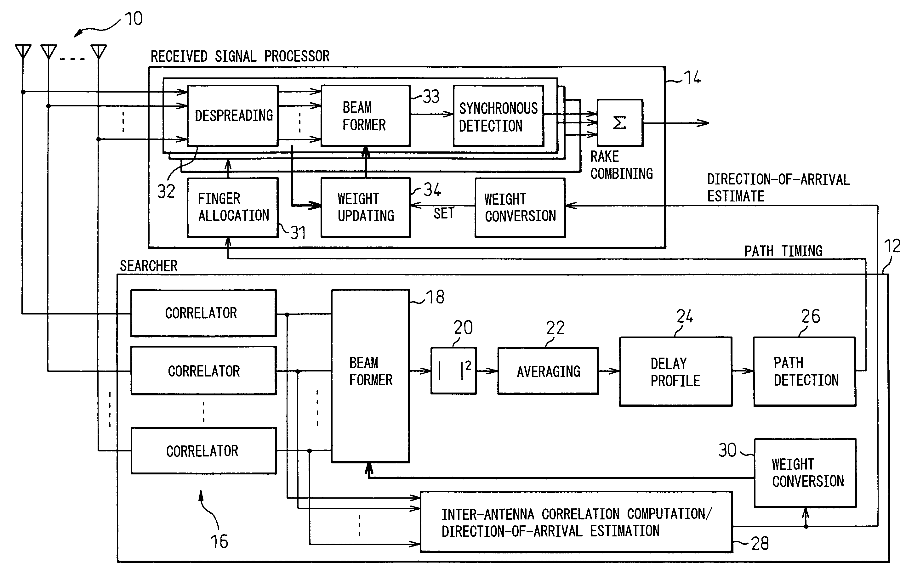
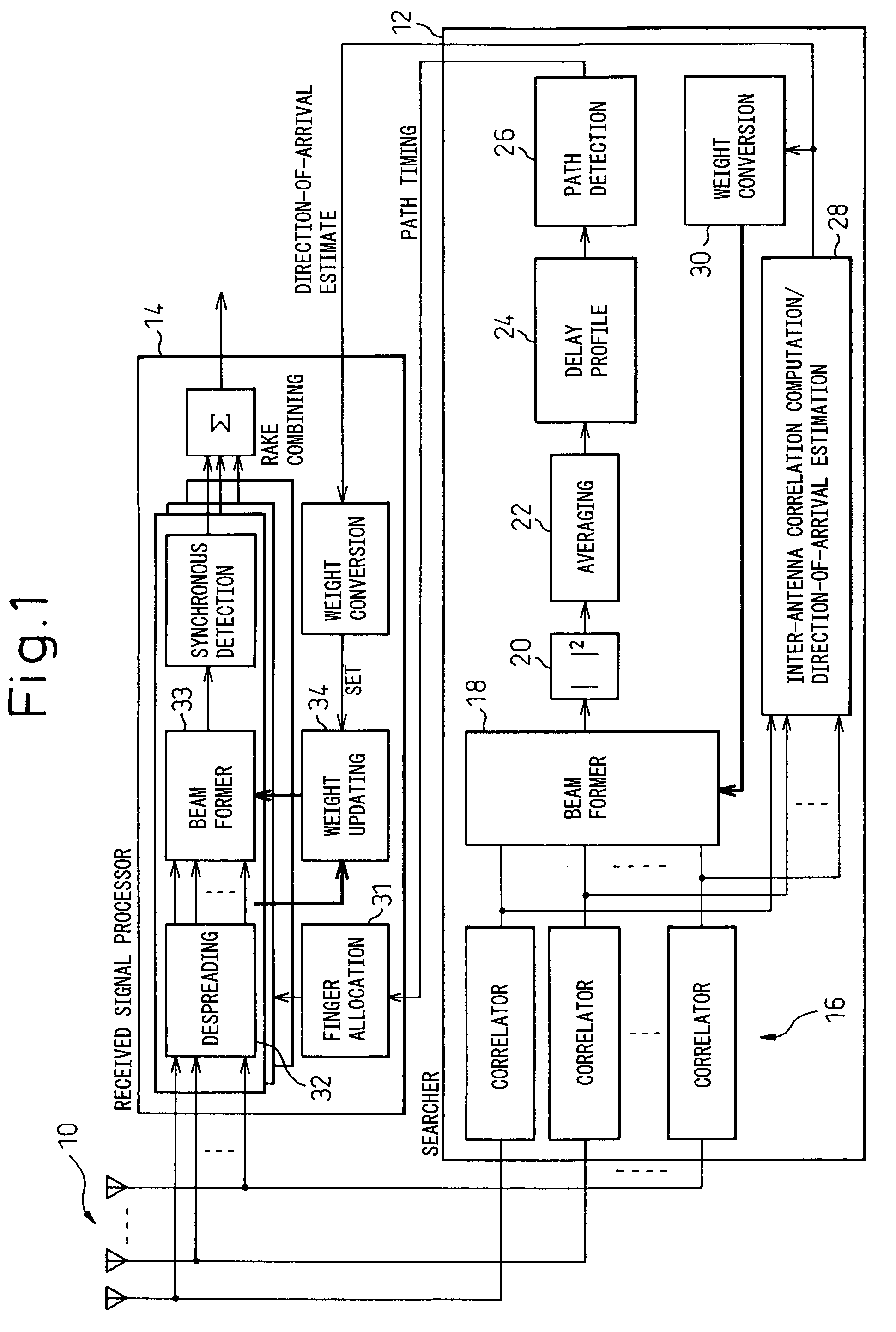
[0018]FIG. 1 shows the configuration of a receiver according to one embodiment of the present invention.

[0019]A radio-frequency signal received by each antenna in an array antenna 10 is first converted by a frequency converter and a quadrature demodulator, not shown, into a baseband signal comprising I-phase and Q-phase components, and then sampled and quantized by an A / D converter, not shown, into a complex-valued digital baseband signal which is supplied to a searcher 12 for path timing detection and a received signal processor 14 for adaptive array reception.

[0020]The searcher 12 of the present invention accepts at its inputs all the antenna signals supplied from the array antenna 10, and each received signal is correlated with a spreading code by a correlator 16 provided for each antenna. The correlated signal of each antenna is fed to a beam former 18 which forms a beam in the direction of arrival of the signal; then, by performing power conversion (20) and time averaging (22),...


PUM


Abstract

Correlation with a spreading code is done for each of the signals received by a plurality of antennas forming an array antenna (10); then, beam forming (18) is performed using the result of the correlation, and a delay profile is generated (20, 22, 26) from the result of the beam forming, thereby achieving accurate path detection (26). DOA information obtained for the beam forming (18) can also be used as an initial value to be given to a beam former (33) in a received signal processor (14).

Description

CROSS-REFERENCE TO RELATED APPLICATION[0001]This application is a continuation of PCT / JP03 / 04124, filed on Mar. 31, 2003, the contents being incorporated herein by reference.TECHNICAL FIELD[0002]The present invention relates to path detection and direction-of-arrival estimation techniques for use in a receiving apparatus in wireless communication equipment that uses an array antenna.PRIOR ART[0003]In a DS-CDMA mobile communication system, as the radiowave transmitted from each mobile unit arrives at a base station over multiple paths with different delay times due to reflections from obstacles such as buildings, a technique called RAKE receiving is employed that gathers the received signals from the multiple paths and combines them into one signal. A receiving apparatus that performs RAKE receiving is equipped with a searcher for determining path timing, i.e., the phase of the despreading code to be applied to each RAKE finger. The searcher performs correlation using a matched filte...

Claims


Application Information

Patent Timeline
Patent Type & Authority Patents(United States)
IPC IPC(8): H04B1/00H01Q21/08H04B1/707H04B1/7113H04B1/7117H04B1/712H04B7/02H04B7/08H04B7/10H04W16/28H04W64/00H04W88/08
CPCH01Q21/08H04B1/7117H04B7/086
Inventor TSUTSUI, MASAFUMI
Owner FUJITSU LTD
Why Eureka
Try Eureka