Convertible folded horn enclosure

a horn enclosure and folding technology, applied in the field of loudspeaker enclosures, can solve the problems of increasing the overall weight and construction complexity, splay angles provide physical limitations to the upper frequency limit, and the added complication and weight of including external side walls, so as to achieve high output capability, increase power handling, and high output

Inactive Publication Date: 2009-03-24
MOORE DANA A
View PDF17 Cites 23 Cited by
  • Summary
  • Abstract
  • Description
  • Claims
  • Application Information

AI Technical Summary

Benefits of technology

[0016]The preferred front-loaded embodiment uses full-channel hard surface reflectors to aid in maintaining phase relationships of the given waveform. It is intended to provide the least tortuous horn pathway possible for the waveform to travel within the limitations imposed by footprint size constraints, and to that end, incorporates a single fold comprised of two controlled reflection surfaces.
[0018]The present invention is intended to maximize versatility for high-sensitivity domestic HI-FI, HT, and PA applications where high output is desired in a relatively small enclosure.

Problems solved by technology

The indirect exit channel splay-angles do provide a physical limitation to the upper frequency limit in which it can propagate without apparent distortion.
The inclusion of forward-canted exit channels bears with it the added complication and weight of including external side walls to fully enclose the horn pathway.
This allows for a more generalized placement for the enclosure, while still allowing for ⅛th space placement for achieving the maximum low frequency response, however, it also would greatly increase the overall weight and the-complexity of construction, for relatively little increase in utility.
A particular drawback of using dual 15-inch diameter drivers is that the overall footprint of the device must be increased to accommodate a relatively large (78 square inch) throat area per driver especially if bifurcated at the throat.
The use of smaller throat cross-section channels would tend to limit the maximum sound pressure level due to air overload distortion, and possibly require the use of smaller diameter drivers to compensate.
This object, while technically achievable in the case of a bifurcated-throat design such as the previously cited prior art designs, may not be economically practical due to the complications imposed by the position of the driver(s).
The tradeoff for domestic situations seems to be that low frequencies with relatively high efficiencies typically means a larger enclosure, with the attendant larger footprint, and the tradeoff for PA use is that achieving high SPL's typically means heavier (or multiple) enclosures are required.
It is typically a much smaller venue than a PA application, but shares some of the same issues, such as overall clarity, maximum SPL, and the presentation of the human voice.

Method used


Image

  • Convertible folded horn enclosure
  • Convertible folded horn enclosure
  • Convertible folded horn enclosure

Examples


Embodiment Construction

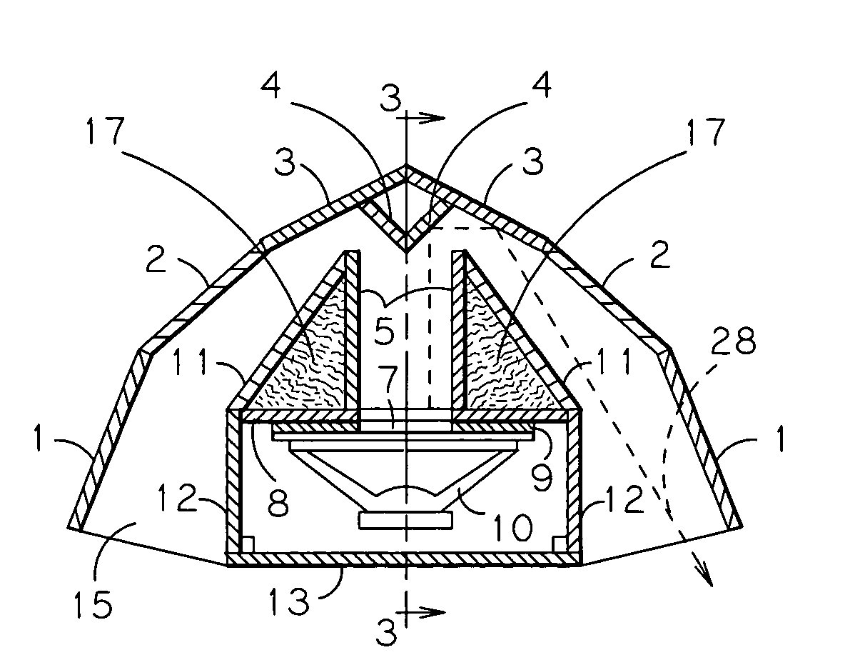
[0033]The current invention consists of a folded exponential-horn enclosure which is symmetrical in both horizontal and vertical planes which is contained within a substantially parabola-shaped outer shell as formed by the rear-channel walls. The overall mouth size for an ⅛ space horn (as measured at the terminal exit) required for the given Fc of 38 Hz is approximately 800 square inches in area (where further waveform expansion presumably takes place outside of the enclosure, as is typical), and therefore, the invention in its optimal state is approximately 39 inches in height, which is also determined to present the optimum height for the effective propagation of a top-mounted midrange and / or high frequency horns to a seated audience.

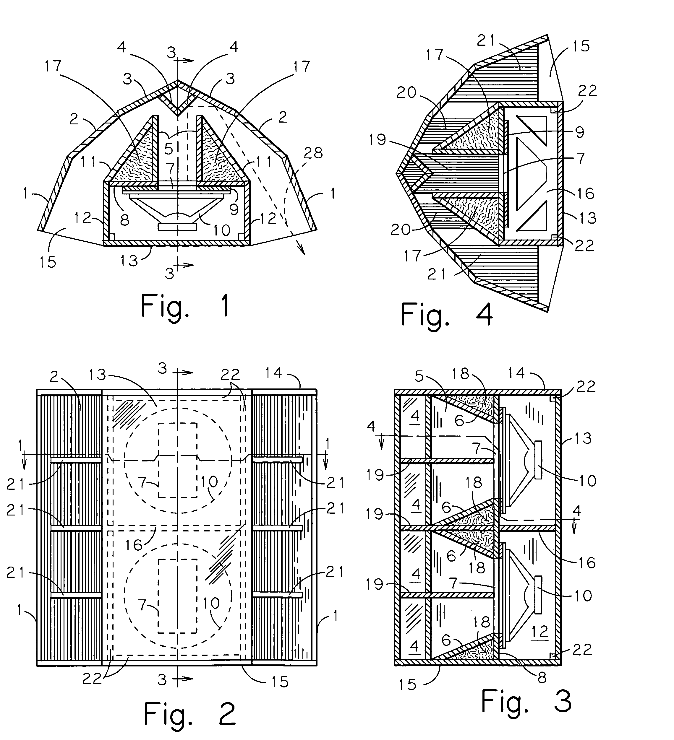
[0034]The preferred embodiment of the invention can be seen in FIGS. 2, 3, 9 and 10. The preferred embodiment of the invention embodies two 15-inch drivers needed to achieve the appropriate channel size at the rear of the enclosure. The invention, bei...


PUM


Abstract

A low frequency exponential bass horn enclosure employing a large area unitary throat pathway, bifurcated at a substantially parabolic rearward channel wall, convertible to a front-loaded or rear-loaded configuration by the use of interchangeable parts, with driver access from the front. Intended for corner placement, however, fully enclosed horn channel allows for floor use. The axially-centered throat expands vertically, exhausts rearward, and is bifurcated at the back of the enclosure with two hard reflection points, comprising a single fold, in which the vertically arranged horn terminus exhausts with a forward-canted splay angle around a partially rectangular back chamber.

Description

BACKGROUND OF THE INVENTION[0001]The present invention relates to loudspeaker enclosures of the low frequency exponential folded horn type primarily intended for corner placement, however is capable of free-standing use as needed. In particular, the present invention features a relatively large-area unitary throat pathway which is bifurcated horizontally at the rear of the enclosure, and exhausts in a relatively forward direction.[0002]The Klipsch and Delgado AES paper, “A Revised Low-Frequency Horn of Small Dimensions”, Vol. 48, No. 10, October 2000, describes a dual 12-inch driver folded horn enclosure featuring throat bifurcation of the horn channels which are horizontally folded. A defining feature of the device is the forward-canted terminal channels exiting on each side of a central planar baffle. The use of forward-canted exit splay angles is explained as providing an increase in upper band pass frequency response by more direct wave propagation to the audience. Due to the th...

Claims


Application Information

Patent Timeline
Patent Type & Authority Patents(United States)
IPC IPC(8): H04R1/02G10K11/28
CPCH04R1/2865H04R1/30
Inventor MOORE, DANA A.
Owner MOORE DANA A
Why Eureka
Try Eureka