Arrangement and a method for coupling light into a plate-like light guide

a technology of arrangement and light guide, which is applied in the direction of optical light guide, optics, instruments, etc., can solve the problems of poor total in-coupling efficiency, limitation of specific polarization states of light, and far from a generally applicable solution for coupling light into thin light guide, and achieve cost-effective effects

Active Publication Date: 2017-06-20
NANOCOMP
View PDF15 Cites 1 Cited by
  • Summary
  • Abstract
  • Description
  • Claims
  • Application Information

AI Technical Summary

Benefits of technology

[0013]According to the present invention, the arrangement further comprises a deflection member arranged to deflect the light beam initially diffracted by the in-coupling diffraction grating, before it hits the in-coupling diffraction grating again, out of the path determined by the in-coupling diffraction grating. Said path determined by the in-coupling diffraction grating comprises naturally the initial direction of the in-coupled light beam, but includes also the propagation direction of the in-coupled light after a reflection at a light guide surface coplanar with the in-coupling diffraction grating. The purpose of the deflection member is to reduce cut-coupling of the already in-coupled light through the in-coupling diffraction grating when hitting it again. Deflecting out of said path means that the deflected beam is no more in the direction of effective function of the in-coupling diffraction grating. Thus, the reverse coupling out from the light guide through the in-coupling diffraction grating is inefficient, thus leading to highly increased total coupling efficiency in comparison to a conventional arrangement based on one single grating only.
[0015]Preferably, the deflection member comprises a deflecting diffraction grating. By means of a diffraction grating, the desired deflection can be realized effectively and accurately. For example, in the case of the in-coupling and deflecting diffraction gratings each consisting of straight and parallel grating lines and being placed on the coplanar opposite sides of the light guide, the deflection can be implemented simply by having the grating geometries being rotated, e.g. perpendicularly, with respect to each other. In addition to or instead of a diffraction grating, the deflecting member can also comprise different kinds of tilted facets or other optical elements providing effects other than diffraction.
[0019]In one preferred embodiment, the in-coupling diffraction grating and the deflecting member both are optimized to maximize the total diffraction efficiency for unpolarized incident light. This means that the function of the arrangement is not dependant on some specific polarization state of the incoming light. This maximizes the versatility of the arrangement Naturally, it is also possible to optimize each of the in-coupling diffraction grating and the deflecting member for any polarization state in accordance with the requirements of the actual application. Again, optimizing the gratings for unpolarized or for some specific polarization is of standard routines for those familiar with the diffractive optics. Thus, no detailed description about how to do it is needed here.
[0024]To summarize, the present invention provides numerous essential advantages over the prior art solutions. The in-coupling area of the arrangement can be far larger than in the conventional solutions suffering from undesired out-coupling in cases the incident light beam is substantially wider than the thickness of the light guide. The arrangement and method according to the present invention are not limited to any specific polarization state of the light and the basic inventive idea can be applied also to non-coalmated and broadband light. The grating and deflection member types can be chosen freely to meet the actual requirements of the application at issue. A structure according to the present invention can be processed with standard manufacturing techniques suitable for cost-effective mass-production without any particular and complex extra steps.

Problems solved by technology

This leads to great losses resulting in a poor total in-coupling efficiency.
However, in this kind of arrangement, the in-coupled light beam disperses in all directions in the plane of the waveguide without any possibility to confine its propagation in some particular direction.
However, an essential drawback of this solution is the limitation to specific polarization states of the light.
However, due to the thick substrate necessitated and the actually rather complex grating design needed to execute the functions described above, this particular approach is far from a generally applicable solution for coupling light into thin light guides.

Method used


Image

  • Arrangement and a method for coupling light into a plate-like light guide
  • Arrangement and a method for coupling light into a plate-like light guide
  • Arrangement and a method for coupling light into a plate-like light guide

Examples


Embodiment Construction

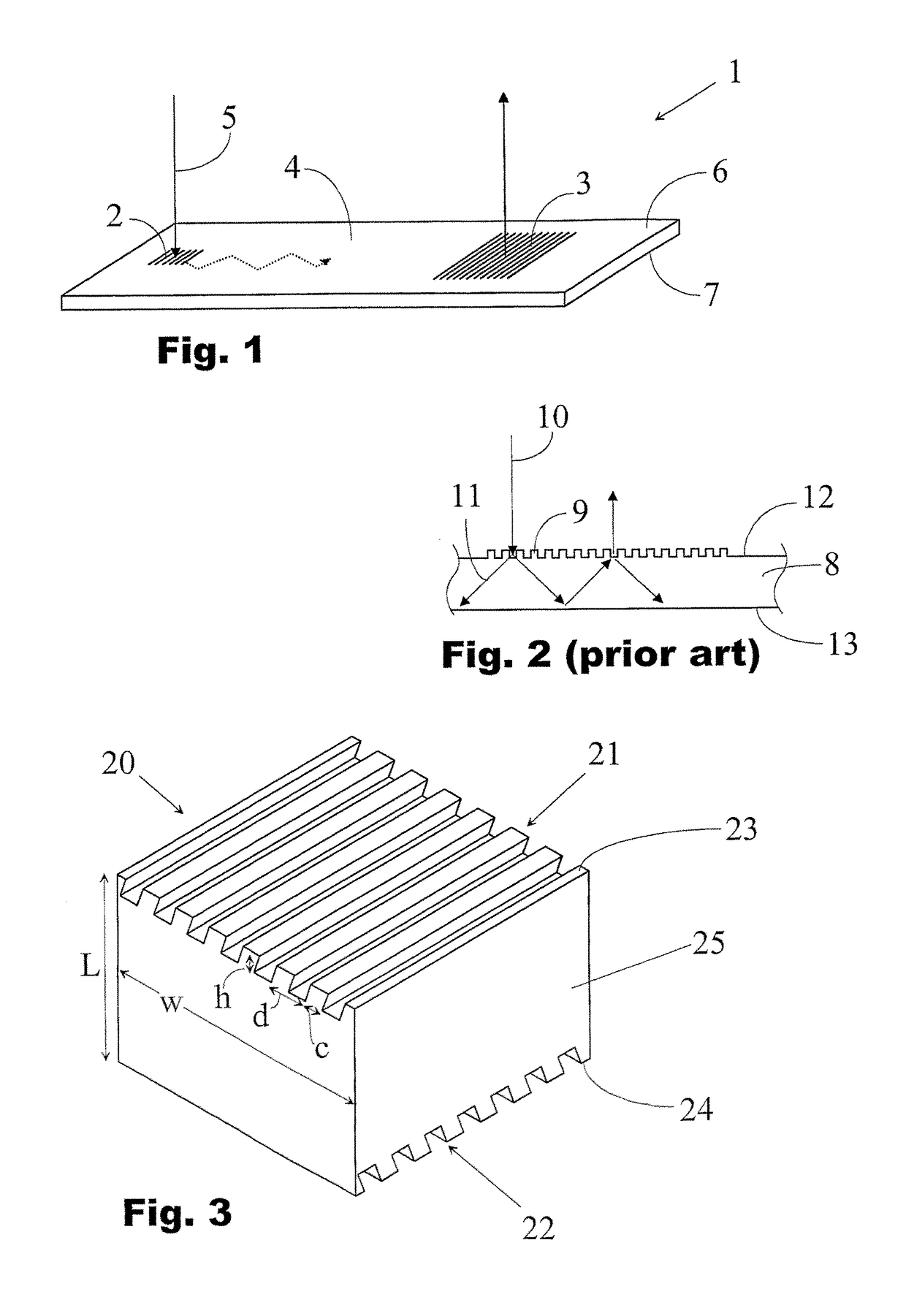
[0030]In FIG. 1, an optical device 1 having an in-coupling region 2 and an out-coupling region 3 arranged on a thin light guide 4 is shown. The purpose of the in-coupling region is to diffract light 5 incident on it into the light guide in a direction which allows the diffracted light to propagate within the light guide via total internal reflections at the surfaces 6, 7 of the light guide. Correspondingly, the intended function of the out-coupling region is to couple the light propagating within the light guide again out of it. This kind of arrangement can be used e.g. in virtual displays or different kinds of illumination applications. Besides the basic configuration of FIG. 1, in some applications there can be several cut-coupling regions around the in-coupling region.

[0031]The main problem related to arrangements shown in FIG. 1 is that there has not been available a solution for effective in-coupling in cases where the light guide thickness is substantially smaller than the des...


PUM


Abstract

An arrangement (20) for coupling light into a plate-like guide (25) having two surfaces (23, 24) on opposite sides of the light guide comprises an in-coupling diffraction grating (21) for diffracting an external light beam (26) incident on said in-coupling diffraction grating into the light guide in a direction enabling the in-coupled light beam to propagate within the light guide via total internal reflections at the light guide surfaces (23, 24). According to the present invention, the arrangement further comprises a deflection member (22) arranged to deflect the beam (27) initially diffracted by the in-coupling diffraction grating (21), before it hits the in-coupling diffraction grating again, out of the path determined by the in-coupling diffraction grating in order to reduce out-coupling of the already in-coupled light through the in-coupling diffraction grating.

Description

FIELD OF THE INVENTION[0001]The present invention relates to coupling light into optical light guides, more particularly to coupling arrangements utilizing diffractive optics for coupling light into thin plate-like light guides.BACKGROUND OF THE INVENTION[0002]There are a number of applications where effective coupling of light into a light guide is desired. Some examples include different kinds of backlights and virtual displays designed to re-distribute light originally emitted e.g. by a LED (Light Emitting Diode).[0003]A traditional approach is to feed the light into a plate-like light guide through its edge which gives a high coupling efficiency especially in the case of a light guide thicker than the beam size. However, in many applications it is the case that the thickness of the light guide is smaller than the size of the light beam to be coupled in. In these cases it is desirable to couple the light through the top or bottom surface of the light guide. The simplest solution ...

Claims


Application Information

Patent Timeline
Patent Type & Authority Patents(United States)
IPC IPC(8): G02B6/34F21V8/00
CPCG02B6/0016G02B6/34
Inventor KUITTINEN, MARKKULAAKKONEN, PASI
Owner NANOCOMP
Why Eureka
Try Eureka