High gradient magnetic separator

a magnetic separator and gradient technology, applied in the direction of magnetic separation, separation process, filtration separation, etc., can solve the problems of limited fluid flow speed, difficult removal of particles with high remnant magnetism, and limited removal of particles during flushing, so as to improve the release of magnetic particles

Active Publication Date: 2009-03-24
KERNFORSCHUNGSZENTRUM KARLSRUHE GMBH
View PDF9 Cites 22 Cited by
  • Summary
  • Abstract
  • Description
  • Claims
  • Application Information

AI Technical Summary

Benefits of technology

[0016]For the cleaning of the matrix which is necessary in certain intervals, the provision of the relatively movable groups of separation areas mentioned above represent a significant improvement.
[0017]The matrix is cleaned preferably in a counter-current principle using a flushing fluid wherein the relative movement of at least two of the separation area structures generates in the flushing fluid turbulence, which, in combination with inertia—, that is centrifugal and gravity forces significantly enhances the release of the magnetic particles from the separation surfaces. Even with some magnetism remaining, this permits cleaning even under the influence of a magnetic field. In certain cases only the provision of such additional forces makes the release possible.

Problems solved by technology

In addition, the desire to keep the volume of the flushing fluid as small as possible, and to hold the required pumping power down the amount of the flushing fluid used and the flow speed of the fluid that can be obtained during flushing are limited.
As a result, removal of the particles is only incomplete.
Particularly particles with a high remnant magnetism are hard to remove.
Consequently, these particles continue to strongly adhere to the matrix wires, which detrimentally affects the clean-up efficiency to a significant degree.

Method used


Image

  • High gradient magnetic separator
  • High gradient magnetic separator
  • High gradient magnetic separator

Examples


Embodiment Construction

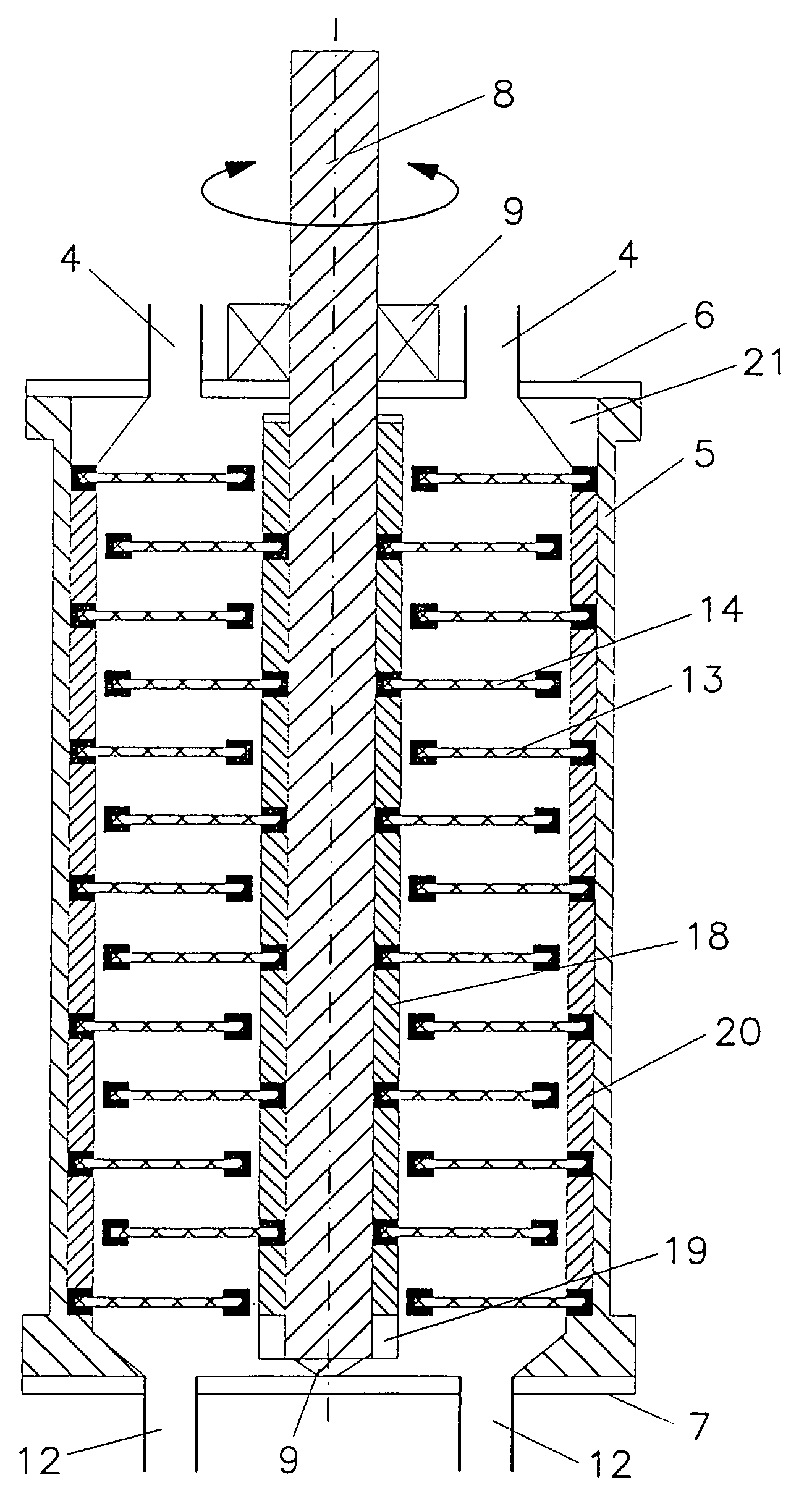
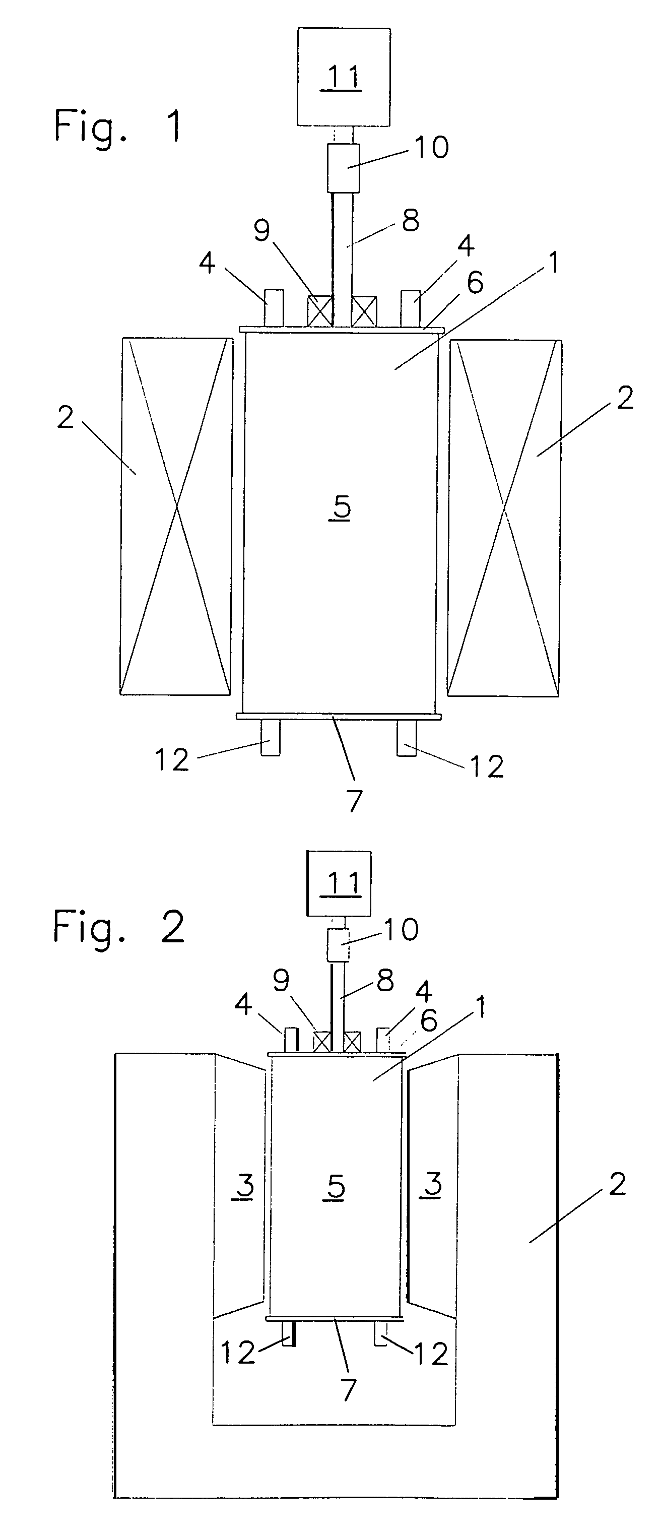
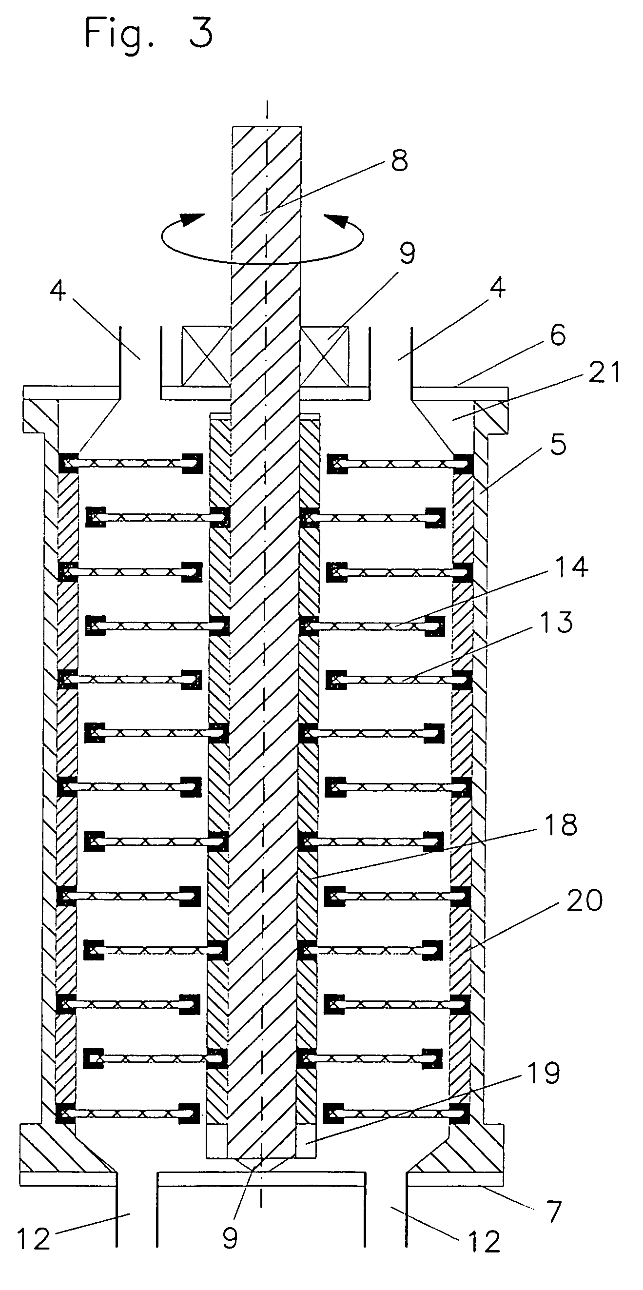
[0024]As shown in FIGS. 1 and 2, the high-gradient magnetic separator 1 is disposed in the direct effective range of a magnetic system 2, which serves as a field source. As magnetic field source preferably electromagnets (FIG. 1), superconductive magnetic systems or permanent magnetic systems (FIG. 2) are used wherein the high gradient magnetic separator 1 is disposed in the magnetic coil opening or, respectively, between the pole shoes 3.

[0025]The actual high gradient magnetic separator comprises several partial units, that is, an essentially cylindrical housing 5 which is closed axially by a lid 6 and a bottom plate 7. A shaft 8 is rotatably supported concentrically in the housing 5, that is, in the shown embodiment by bearing 9 in the lid and or the bottom plate 7 in a sealed manner and is connected to a drive 11 by way of a clutch 10. The shaft, the housing, the lid and the bottom plate all consist of non-magnetic material.

[0026]The core unit of the high gradient magnetic separa...


PUM

PropertyMeasurementUnit
particle sizesaaaaaaaaaa
sizeaaaaaaaaaa
frequencyaaaaaaaaaa

Abstract

In a high-gradient magnetic separator for the selective separation of magnetic particles from a suspension which is conducted through a matrix of plate-like separation structures of a magnetic material which are disposed in a magnetic field and through which the suspension is conducted, alternate plates of the separation structures are movable relative to the other plates which are stationary and are all mounted on a carrier by which they can be moved relative to the stationary plates at least during cleaning of the plates for the removal of magnetic particles collected on the plates.

Description

BACKGROUND OF THE INVENTION[0001]The invention relates to a high-gradient magnetic separator for the selective separation of magnetic particles from a suspension.[0002]The separation of ferro-, ferri- or para-magnetic particles from liquid or gaseous fluids by magnetic separators is a basic concept of chemical engineering used in numerous variants. A particular advantage of the principle of the magnetic separation resides in the possibility to selectively separate magnetic particles from a mixture with other, non-magnetic particles. The selection of the magnetic separator is based on the size and the magnetic properties of the particles.[0003]Relatively large and highly magnetic particles such as magnetite ores with particle sizes >75 μm can be separated with simple drum or band separators. Finer, strongly magnetic particles up to a size of 10-20 μm can still be separated from an aqueous suspension by special drum separators. Yet finer particles in the micrometer range (about 0.1...

Claims


Application Information

Patent Timeline
Patent Type & Authority Patents(United States)
IPC IPC(8): B03C1/00
CPCB03C1/03B03C1/032B03C1/0332
Inventor FRANZREB, MATTHIASREICHERT, CHRISTIAN
Owner KERNFORSCHUNGSZENTRUM KARLSRUHE GMBH
Why Eureka
Try Eureka