
Secondary battery module

a secondary battery and module technology, applied in the field of secondary batteries, can solve the problems of reduced manufacturing efficiency, high work load of manufacturing a module, and large amount of time, and achieve the effect of improving the secondary battery modul

Active Publication Date: 2009-03-24
SAMSUNG SDI CO LTD
View PDF18 Cites 48 Cited by
  • Summary
  • Abstract
  • Description
  • Claims
  • Application Information

AI Technical Summary

Benefits of technology

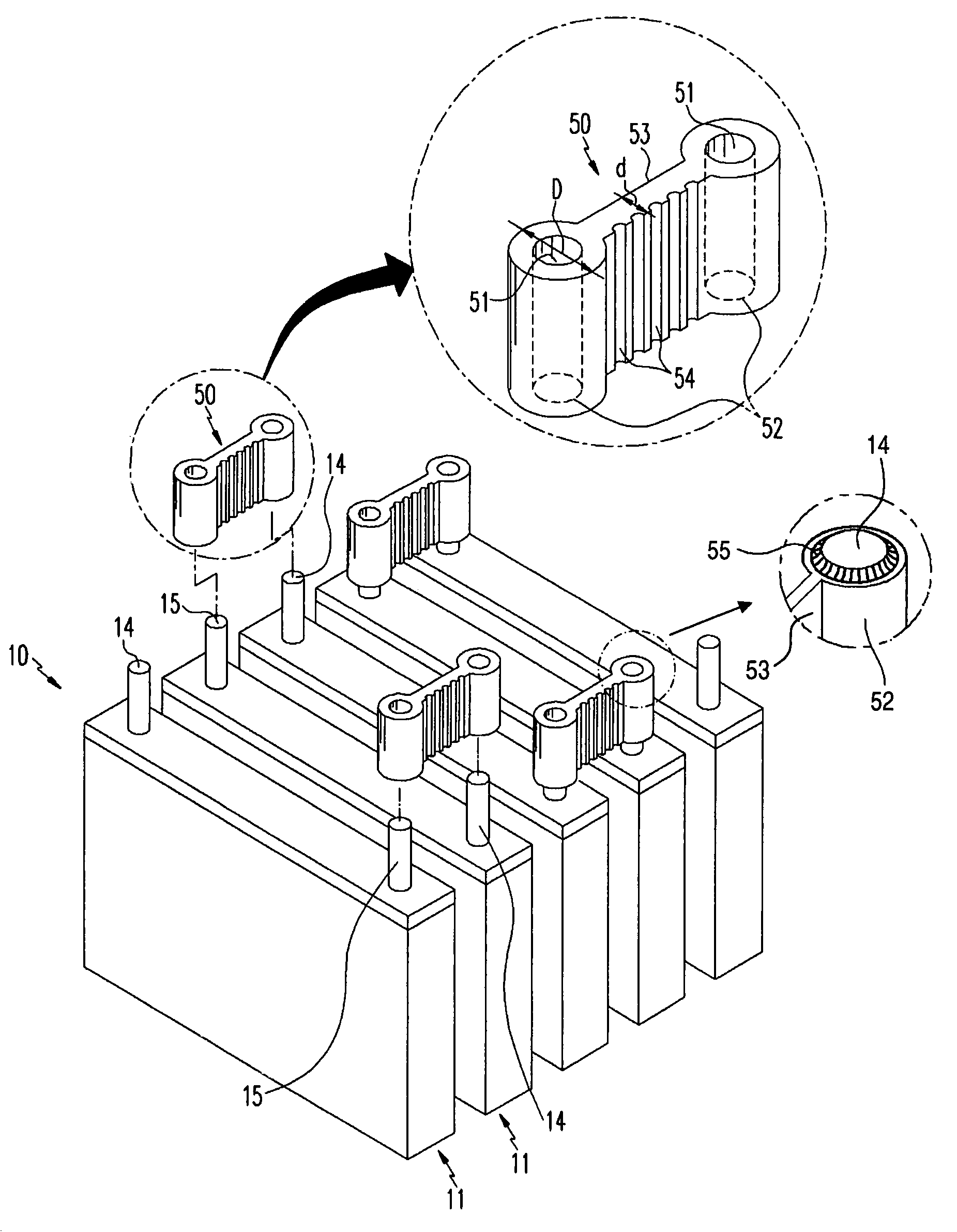
The present invention provides an improved secondary battery module with simplified cell connection and replacement work. The connector has a surface contact portion that maximizes electrical conductivity with the terminals of the unit cells. The connector can be fixed to the terminals by forced insertion or welding. The unit cells are serially connected to each other, and the depth of the groove or hole in the connector prevents electrical connection between the cap assembly and the connector. The terminals have a coating layer with high electrical conductivity, and the cross-section of the groove or hole is thicker than the bridge connecting the terminals to facilitate bending. The size of the cross-section of the groove or hole becomes continuously smaller along one direction to form an inclined plane, and the terminals are inserted into the grooves or holes of the connector so that two adjacent unit cells are serially connected, and the connector is fastened and fixed to the unit cells by the strong frictional force between the inner circumference of the groove or hole of the connector and the outer circumference of the terminal.

Problems solved by technology

Since each terminal of the unit cell in the secondary battery module needs screw fixation, workload for manufacturing a module is high and large amount of time is required.
In addition, when some unit cells in the secondary battery module do not work properly, it is necessary to separate the malfunctioning unit cells from the other to replace them with new unit cells or the repaired unit cells.
However, this requires unscrewing the nut from the terminal and then screwing the nut to the terminal, which is inconvenient so that the manufacturing efficiency is decreased.
In addition, since the conventional conductive member has a plate shape, the contact area can not be increased when the conductive member contacts the terminal.
Accordingly, it has a problem that the electrical conductivity between the terminal and the conductive member is lowered.
Especially, as the secondary battery module used for motor driven devices such as a hybrid electric vehicle requires tens of unit cells, the above problems are more serious.

Method used


Image

  • Secondary battery module
  • Secondary battery module
  • Secondary battery module

Examples


Embodiment Construction

[0045]Reference will now be made in detail to the embodiments of the present invention, examples of which are illustrated in the accompanying drawings. The embodiments are described below to explain the present invention by referring to the figures.

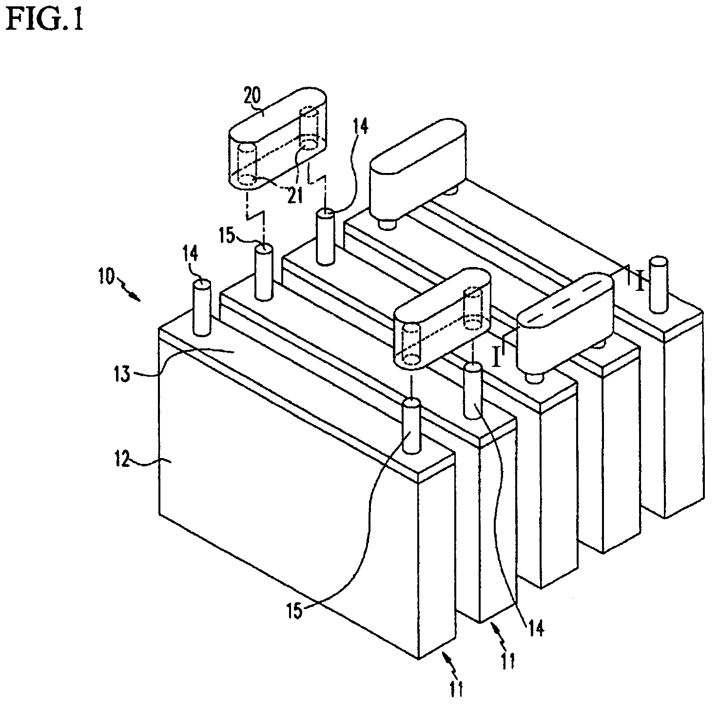
[0046]FIG. 1 is an exploded perspective view of a secondary battery module according to a first embodiment of the present invention, FIG. 2 is a partial cross-sectional side view taken along the line I-I of FIG. 1, and FIG. 3A is a partial plan view of the secondary battery modules according to the shapes of a groove of a connector and a terminal of the first embodiment of the present invention.

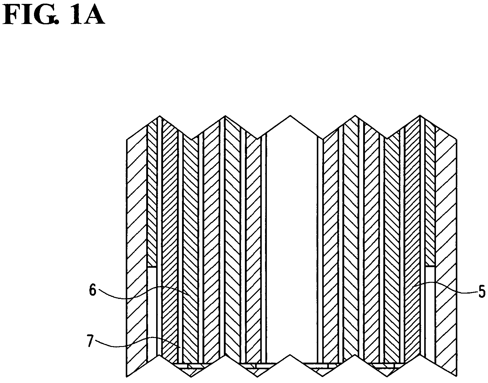
[0047]A bulk size secondary battery module 10 includes unit cells 11, each of which has an electrode assembly including a positive electrode, a negative electrode and a separator interposed between those two electrodes (an exemplary illustration of a positive electrode 5, a negative electrode 6 and a separator 7 is shown in FIG. 1A), a case 12 havi...


PUM

PropertyMeasurementUnit
sizeaaaaaaaaaa
energy densityaaaaaaaaaa
poweraaaaaaaaaa

Abstract

A secondary battery module includes a plurality of unit cells, and a connector electrically connecting the unit cells to each other. The connector has a surface contact portion, and the shape of the surface contact portion corresponds to the shape of terminals of the unit cell. The connector is fastened to a terminal of the unit cell by insertion.

Description

CLAIM OF PRIORITY[0001]This application makes reference to, incorporates the same herein, and claims all benefits accruing under 35 U.S.C. 119 from two applications for letters patent entitled SECONDARY BATTERY AND SECONDARY BATTERY MODULE earlier filed respectively in the Korean Intellectual Property Office on 4 May 2004 and 29 Mar. 2005 and there, duly assigned Serial Nos. 10-2004-0031309 and 10-2005-0025916, respectively.BACKGROUND OF THE INVENTION[0002]1. Technical Field[0003]The present invention relates to a secondary battery, and more particularly, to a secondary battery module of high power and bulk size in which the connecting structure between the unit cells is improved.[0004]2. Related Art[0005]The non-aqueous electrolyte secondary batteries of high energy density have recently been developing as high power secondary batteries.[0006]Several to tens of the high power secondary cells (hereinafter “unit cell”) are serially connected to form one module for motor drive of the ...

Claims


Application Information

Patent Timeline
Patent Type & Authority Patents(United States)
IPC IPC(8): H01R24/00H01M2/10H01R11/28H01R13/648
CPCH01R11/288H01M50/502H01M50/209H01M50/503
Inventor KIM, YONG-SAM
Owner SAMSUNG SDI CO LTD
Learn More