Flat cable clamp

a cable clamp and cable technology, applied in the direction of flat/ribbon cables, cables, cable connections, etc., can solve the problem of difficult engagement of 2 pieces of the main body of the clamp

Inactive Publication Date: 2009-03-24
YAZAKI CORP
View PDF18 Cites 25 Cited by
  • Summary
  • Abstract
  • Description
  • Claims
  • Application Information

AI Technical Summary

Benefits of technology

[0009]The present invention is made in view of the above-described situation, and its objective is to provide a flat cable clamp which can easily carry out a mutual engagement operation of members for clamping down a flat cable over preventing flip-flop of the flat cable which is clamped down (i.e., unstable fixing).
[0022]According to the flat cable clamp of the above-described configuration (1), on the occasion that at least 1 piece of the cable pressing protrusion is engaged with the clamp main body and the cover, the bridge portion is pressed in its thickness direction so as to be bent toward an inner surface of the other of the clamp main body and the cover, and by that means, the flat cable is held down on an inner surface of the other of the clamp main body and the cover, and therefore, flip-flop of the flat cable which is clamped down by the clamp main body and the cover (i.e., unstable fixing) is prevented, and in addition to that, there is no need to reduce an over-stroke of the locking mechanism, and therefore, it is possible to secure an over-stroke necessary for the locking mechanism over suppressing flip-flop of the flat cable, and thus, it is possible to easily carry out an engagement operation of the clamp main body and the cover over clamping down the flat cable.
[0023]According to the flat cable clamp of the above-described configuration (2), an refuge space for allowing bending of the bridge portion is formed between an inner surface of the other of the clamp main body and the cover, and the bridge portion, and it is possible to secure an over-stroke which is sufficient for the locking mechanism, and therefore, it is possible to easily carry out an engagement operation of the clamp main body and the cover over clamping down the flat cable.
[0024]According to the flat cable clamp of the above-described configuration (3), an over-stroke between the catching surfaces is equivalent to such a distance that an forefront surface of the at least one cable holding-over protrusion moves toward an inner surface of the other of the clamp main body and the cover, in such a situation that the catching surfaces are caught each other and further on the occasion that the clamp main body and the cover are pressed in a direction of clamping down the flat cable, and therefore, it is possible to disposed a desired over-stroke between the catching surfaces, by arbitrarily setting a height of the cable holding-down protrusion.
[0025]Furthermore, in the flat cable clamp of the above-described configuration (3), it is possible to disposed a desired over-stroke having a margin between the catching surfaces, by arbitrarily setting a depth (i.e., a depth of the refuge space) from the bridge portion to an inner surface of the other of the clamp main body and the cover as in the above-described configuration (2).
[0026]According to the present invention, it is possible to provide a flat cable clamp which can easily carry out a mutual engagement operation of members for clamping down a flat cable over preventing flip-flop of the flat cable which is clamped down (i.e., unstable fixing).

Problems solved by technology

However, by configuring in that manner, there is no choice to reduce an over-stroke of the locking mechanism, on the occasion that 2 pieces of clamp main bodies are engaged with each other, and engagement of 2 pieces of the clamp main bodies becomes difficult.

Method used


Image

  • Flat cable clamp
  • Flat cable clamp
  • Flat cable clamp

Examples


Embodiment Construction

[0037]Hereinafter, a preferred embodiment, which relates to the present invention, will be explained in detail on the basis of drawings.

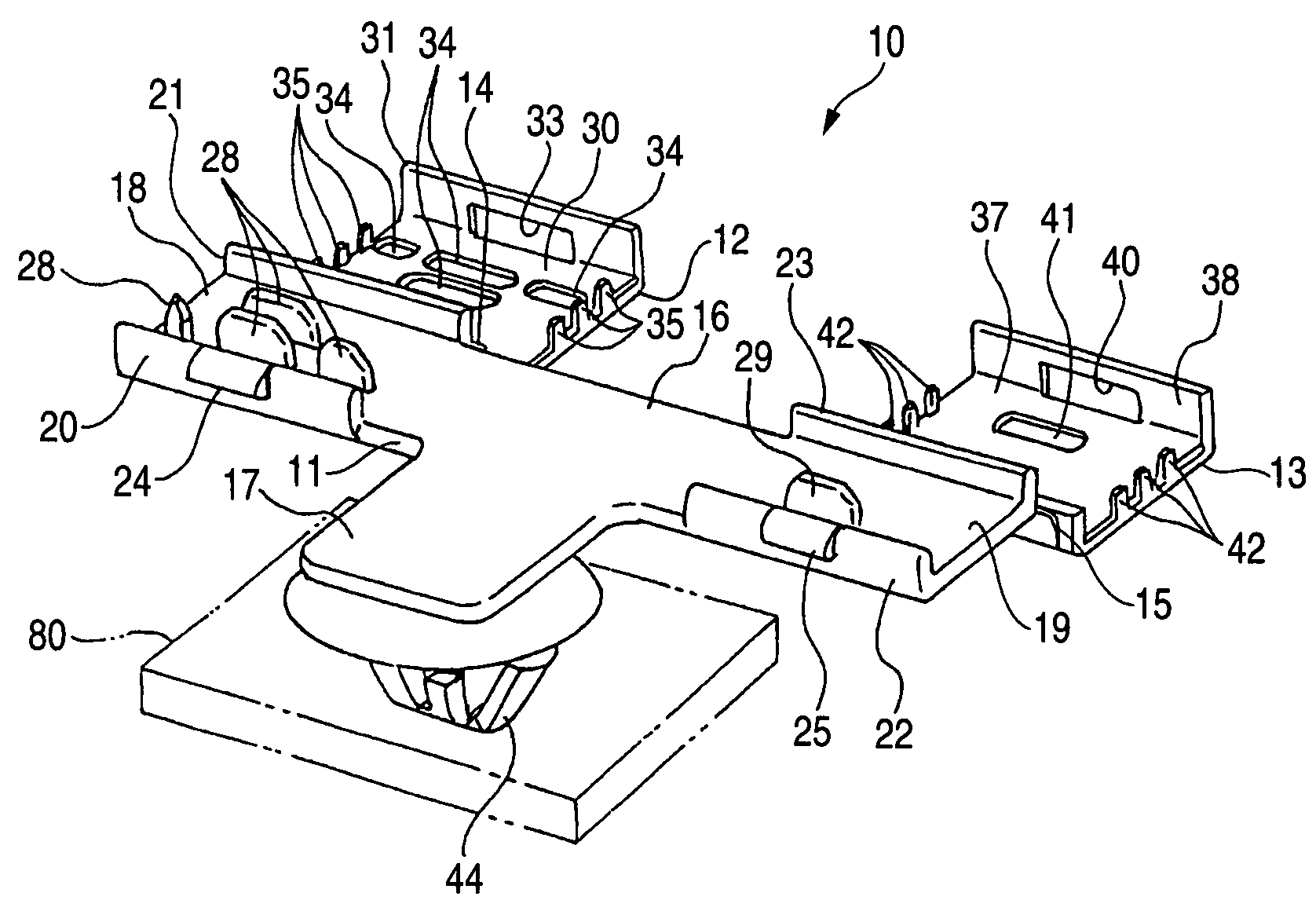
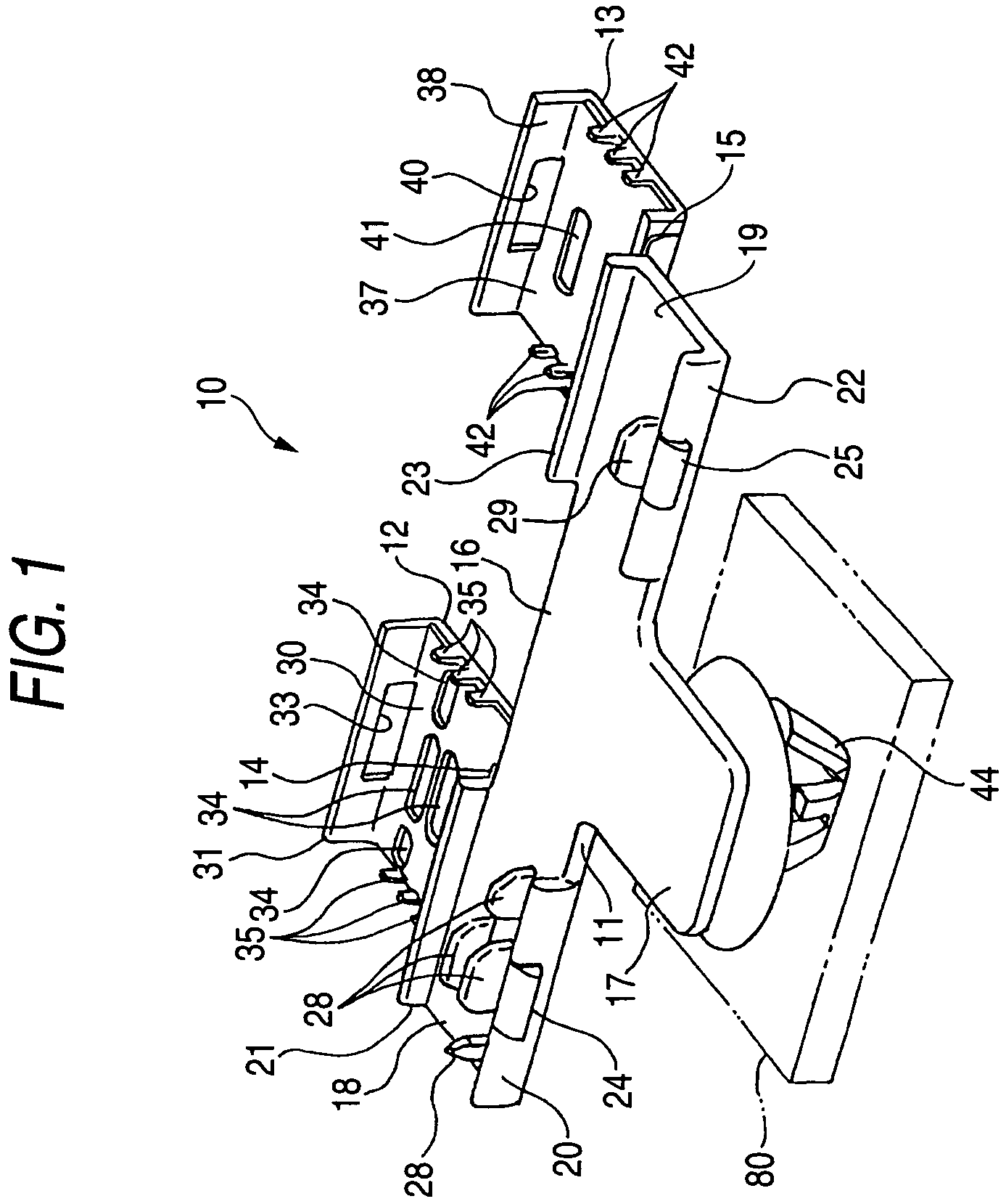
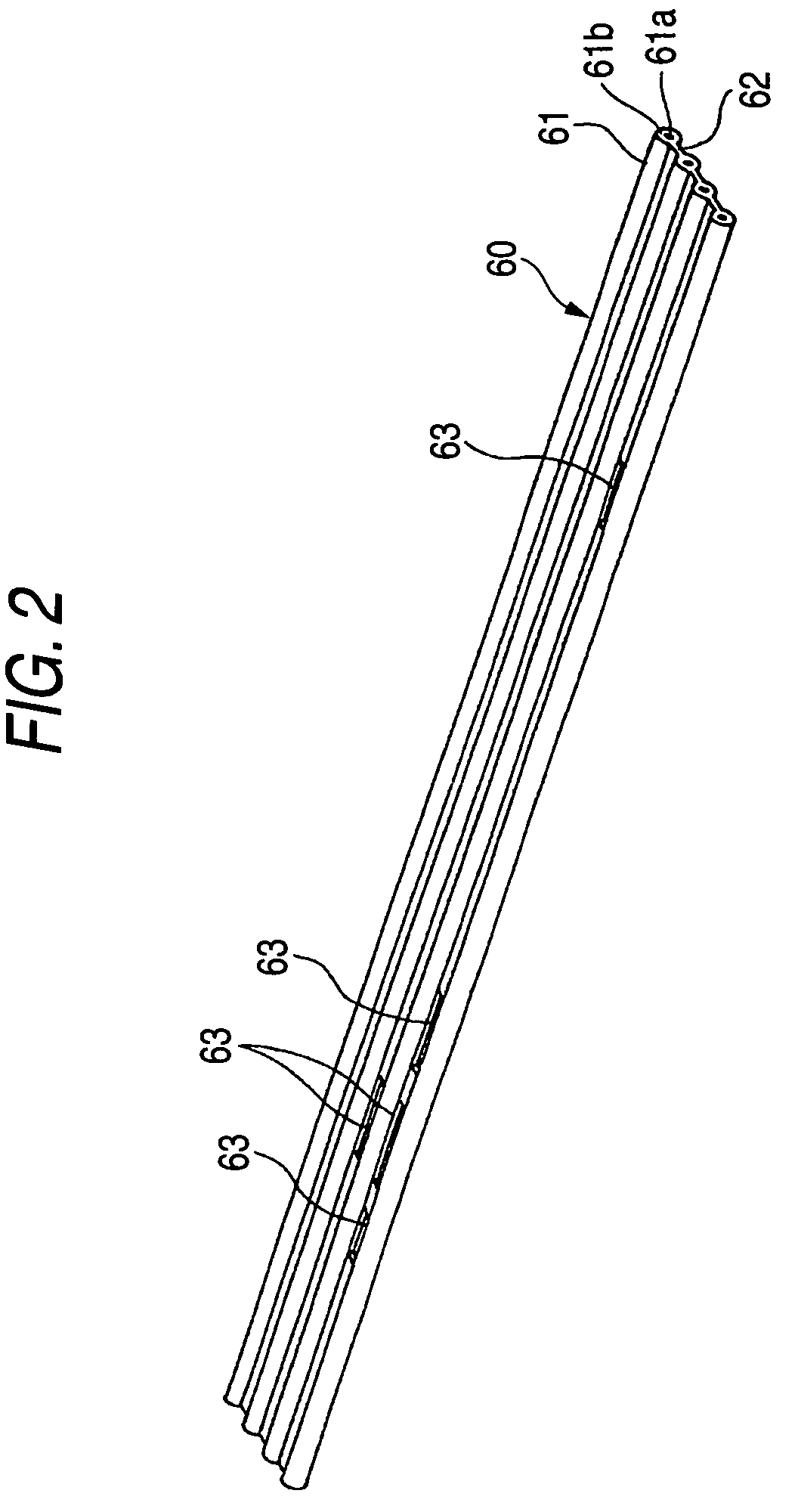
[0038]FIG. 1 is an external appearance perspective view which shows one embodiment of a flat cable clamp that relates to the present invention, in such a situation that its clamp main body and a cover are expanded, and FIG. 2 is an external appearance perspective view of a flat cable which is clamped down by the flat cable clamp of FIG. 1, and FIG. 3 is an external appearance perspective view which shows such a situation that the flat cable of FIG. 2 is clamped down by the flat cable clamp of FIG. 1, and FIG. 4 is a cross sectional view viewed from IV-IV arrow of FIG. 3 (schematic cross sectional view), and FIG. 5 is a cross sectional view viewed from V-V arrow of FIG. 3 (schematic cross sectional view).

[0039]As shown in FIGS. 1 through 5, a flat cable clamp 10, which is one embodiment of the present invention, is a flat cable clamp for fixing a fla...


PUM


Abstract

To provide a flat cable clamp which can easily carry out a mutual engagement operation of members which clamp down a flat cable over preventing flip-flop (i.e., unstable fixing) of the flat cable which is clamped down, on the occasion that a clamp main body 11 and first, second covers 12, 13 of a flat cable clamp 10 are engaged with each other, cable holding-down protrusions 35, 42 press a bridge portion 62 of a flat cable 60 so as for the bridge portion 62 to be bent toward an inner surface of the clamp main body, in its thickness direction. By that means, the flat cable 60 is held down to the inner surface of the clamp main body 11.

Description

BACKGROUND OF THE INVENTION[0001]1. Field of the Invention[0002]This invention relates to a flat cable clamp which is used for fixing a flat cable having flexibility such as FFC (i.e., Flexible Flat Cable) and a ribbon electric cable, to a body to be mounted such as a car body panel.[0003]2. Description of the Related Art[0004]As one of a conventional flat cable clamp, such a thing that a flat cable is clamped down by 2 pieces of clamp main bodies and the flat cable is fixed to a printed board, has been known (e.g., see, JP-A-06-275966 publication).[0005]This flat cable clamp is equipped with 2 pieces of clamp main bodies where an opening portion and a convex portion are formed. According to the flat cable clamp, it is configured in such a manner that the flat cable and the printed board are clamped down between respective surfaces of 2 pieces of the clamp main bodies where the opening portions and the convex portions are disposed, and the flat cable is fixed to the printed board by...

Claims


Application Information

Patent Timeline
Patent Type & Authority Patents(United States)
IPC IPC(8): H02G3/04
CPCH02G3/32B60R16/0215Y10T24/44026
Inventor SUZUKI, KAORU
Owner YAZAKI CORP
Why Eureka
Try Eureka