UV treatment reactor

a technology of uv treatment reactor and reactor, which is applied in the direction of material analysis using wave/particle radiation, chemistry apparatus and processes, instruments, etc., can solve the problems of high dose, high headloss, and needing more lamps, even of lower power

Active Publication Date: 2009-03-24
DE NORA WATER TECH
View PDF18 Cites 17 Cited by
  • Summary
  • Abstract
  • Description
  • Claims
  • Application Information

AI Technical Summary

Benefits of technology

[0009]In this way, the present invention represents a substantial advance over prior UV treatment devices. An embodiment of the invention offers the advantage of a UV reactor for treatment of water that is efficient in design, flexible in operation and relatively low in cost. Another advantage of the invention is to provide an assembly of UV sources wherein the UV Sources are arranged so as to provide a generally uniform dose of UV light being emitted across the cross-section of the reactor, thereby achieving a generally uniform dose, or narrow dose distribution Another object in an embodiment of the present invention is to provide a device having efficient turndown capabilities, i.e., lamps run at reduced or no power to provide efficient turndown. An embodiment of the invention operates with only as many lamps as are needed to achieve a required dose, and can operate with a fewer number of lamps than required in traditional UV reactor systems. It is an object of an embodiment of the present invention to provide an arrangement of baffles that causes the fluid to flow in close proximity to the UV sources, thereby improving dose distribution.

Problems solved by technology

However, a concern in such systems is absorption of UV light by adjacent lamps because light cannot pass upstream and downstream unobstructed.
This method can also impose higher headloss and require more lamps, albeit of lower power.
This method results in a higher pressure drop through the reactor and leaves zones behind the baffles with low or virtually no flow resulting in high doses in these areas, especially when the UV transmittance of the water is high.
It therefore becomes difficult to design a reactor that achieves a narrow dose distribution over the full range of water UV transmittances that the reactor is called on to treat.
However, even in these systems, and UV systems using similar patterns, there are areas where water does not receive a minimum exposure to the UV fluence rate field.
Systems configured with a circular array of UV light sources may also tend to lack efficient lamp turndown capabilities.
Further, in the circular array, turning off two lamps results in irradiance gaps in the flow stream in areas where the lamps are off, as compared to radiance emitted in areas where the remaining lamps may be close to each other.
The uneven dose distribution yields poor efficiency and, in some cases, inadequate treatment levels or untreated water.

Method used


Image

  • UV treatment reactor
  • UV treatment reactor
  • UV treatment reactor

Examples


example 1

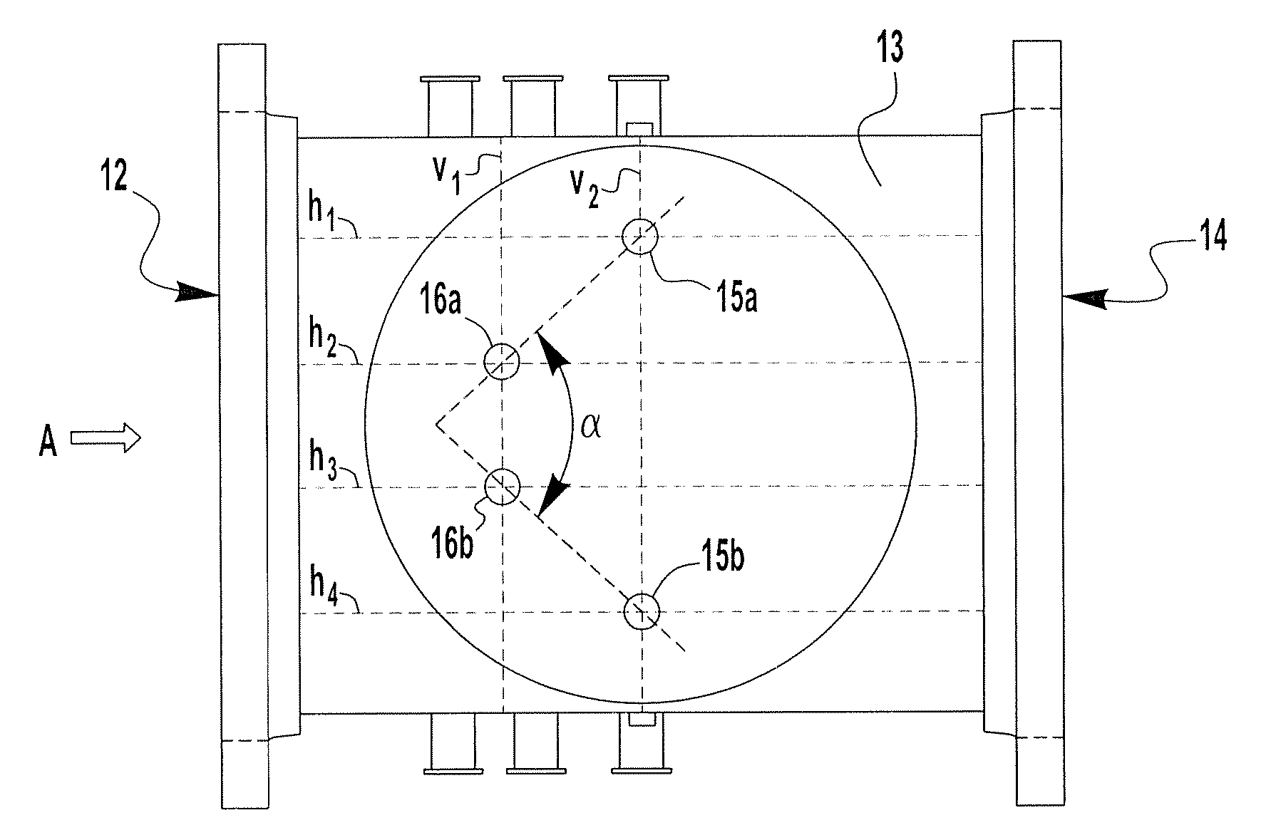
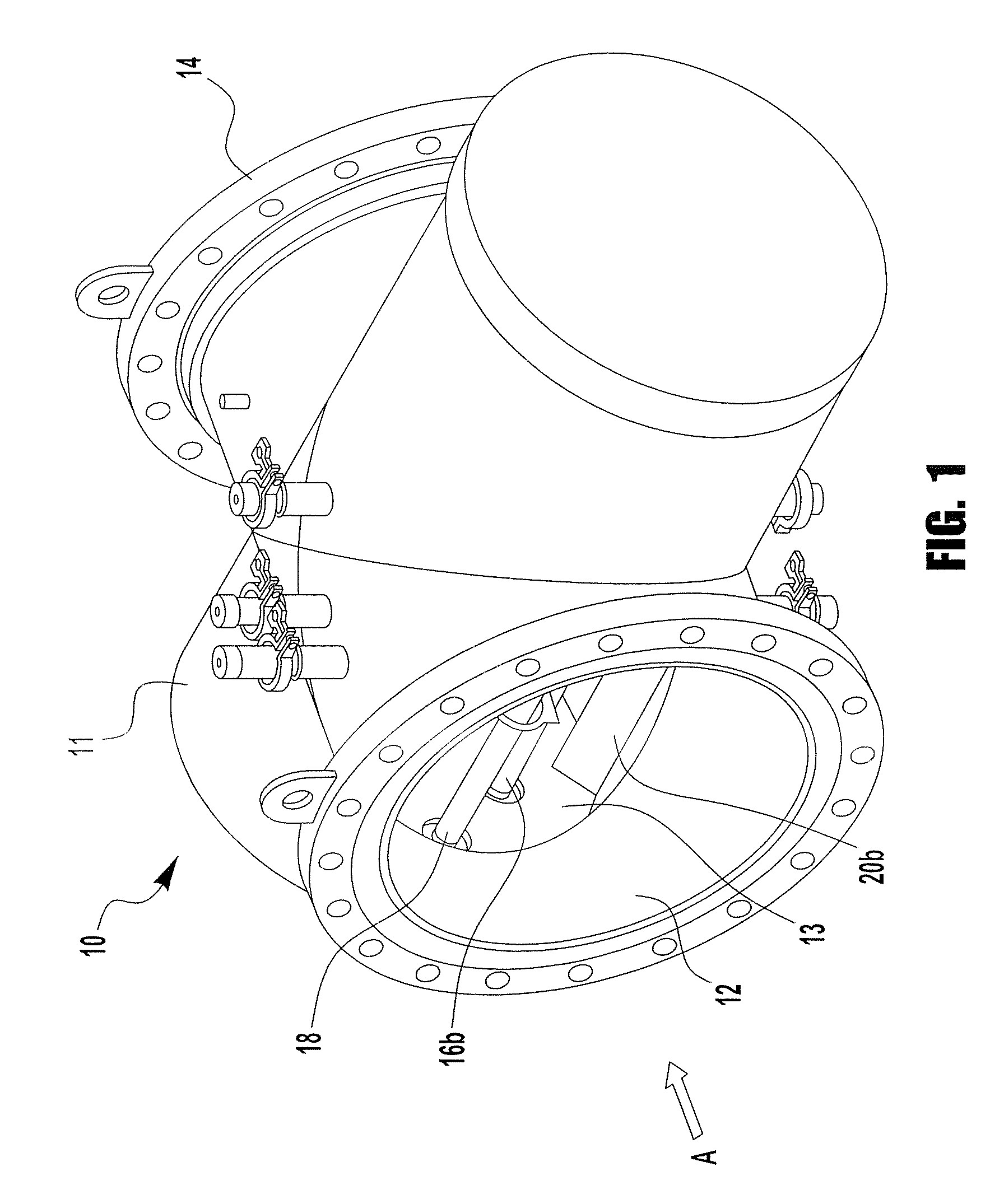
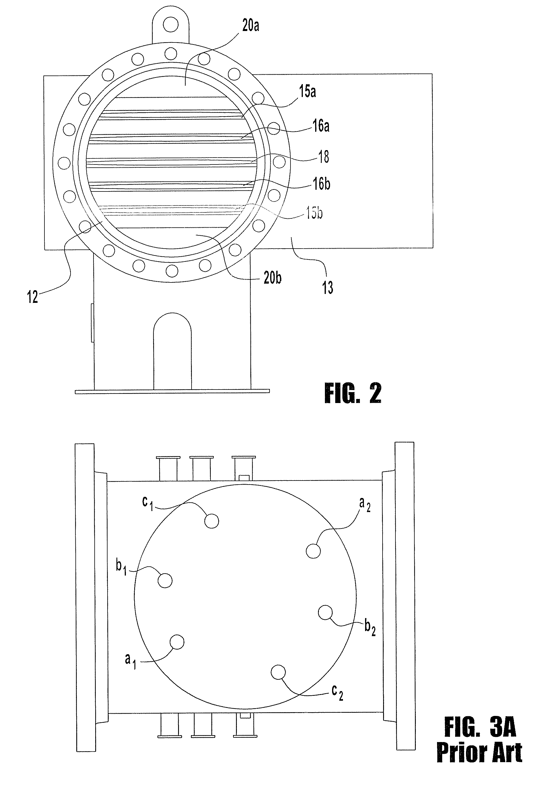
[0034]A reactor with a typical circular array was modified for comparison with an embodiment of the present invention. Such reactors require at least six or more lamps. For purposes of comparison with the present invention, a reactor having a “circular array” was prepared to contain a UV lamp geometry using only five lamps as illustrated in FIG. 3b. In this array of lamps, b1 and b2 are positioned downstream of UV sources a1 and a2 to effect an essentially circular array as compared to a five lamp reactor in the chevron array as embodied in FIG. 5. The span between the lamp pairs was maintained. Computational Fluid Dynamic (CFD) modeling combined with fluence field modeling was used to determine the performance of this reactor when operating with five lamps and with four lamps. Similar tests were conducted on an embodiment of the present invention using five lamps arranged in a chevron pattern as shown in FIG. 5. The results were compared and are summarized in Table 1 below.

[0035]

TA...

example 2

[0038]In an example of the invention, reactor 10 with five UV lamps arranged in a substantially chevron configuration according to this invention was modeled using Computational Fluid Dynamic Modeling to predict performance. The results are summarized in Table 2.

[0039]

TABLE 2Flow, MGD10.8.6.4.2.UV Transmittance, %8790909295No of Lamps operating54321Dose required, mJ / cm24040404040Actual Dose (CFD44.446.648.946.546.7Modeling) at 10 kW / lampLamp power to achieve 409.38.78.48.58.9Dose (CFD Modeling), kW

[0040]With five lamps operating at 10 million gallons per day (MGD) flow and a UV transmittance of 87%, a dose of 44.4 mJ / cm2 is achieved. The lamps can be turned down to 9.3 kW / lamp to achieve the required 40 mJ / cm2 dose. Alternate lamps were turned off, one lamp or pair of lamps at a time, to demonstrate turndown efficacy. First, the front lamp 18 was turned off to provide four operating lamps. These lamps were sufficient in the situation at a flow rate of 8 MGD and UV transmittance of 9...


PUM

PropertyMeasurementUnit
angleaaaaaaaaaa
angleaaaaaaaaaa
angleaaaaaaaaaa

Abstract

An apparatus for treating fluids with UV comprises a housing for receiving a flow of fluid having a fluid inlet, a fluid outlet, a reaction chamber; and an assembly of UV sources positioned substantially perpendicular to the fluid. The assembly includes at least first and second pairs of UV sources located in the reactor chamber. The first pair of UV sources has upper and lower UV sources that are positioned relative to each other at a span that is greater than the span between the upper and lower UV sources in the second pair. The second pair is positioned in either the upstream or downstream flow of fluid such that the plane created by the upper UV sources of each pair of UV sources intersects with the plane created by the lower UV sources of each pair of UV sources Subsequent UV sources or pairs of UV sources may be advantageously used. The apparatus may be combined with a baffle arrangement wherein the baffles are preferably positioned in such a way to direct the fluid now into the treatment area.

Description

FIELD OF THE INVENTION[0001]The present invention relates to an apparatus for treating fluids with ultraviolet (“UV”) light, and in particular provides an apparatus that efficiently distributes UV dose so as to achieve increased treatment effectivenessBACKGROUND OF THE INVENTION[0002]The use of UV radiation to inactivate microorganisms in fluid is known There are several types of UV systems including those that are pressurized, semi-pressurized or not pressurized. Such systems generally rely on lamps positioned in rows submerged in the fluid to be treated, such as drinking water. Regardless of the type of UV system, it is important to deliver as close to an equal amount of UV light (dose or fluence) to all fluid flowing though the system to inactivate any microorganisms. This dose or fluence is equal to the product of the intensity and time. As microorganisms pass though the UV system they are subjected to a range of UV intensities and times resulting in a distribution of doses. Ide...

Claims


Application Information

Patent Timeline
Patent Type & Authority Patents(United States)
IPC IPC(8): G01N21/00
CPCC02F1/325C02F2201/3222C02F2201/3227C02F2201/328
Inventor BIRCHER, KEITH G.
Owner DE NORA WATER TECH
Why Eureka
Try Eureka