Wave configuration for the web of a level frame

a level frame and web technology, applied in the field of level, can solve the problems of increasing the amount of material required, increasing the weight and cost of level manufacture, and molded levels may not have the structural rigidity found in metal or wood levels, so as to reduce the flexing of the level, increase the amount of material used, and increase the strength and rigidity of the level frame

Active Publication Date: 2009-03-31
JOHNSON LEVEL & TOOL MFG
View PDF14 Cites 17 Cited by
  • Summary
  • Abstract
  • Description
  • Claims
  • Application Information

AI Technical Summary

Benefits of technology

[0005]It is an object of the present invention to provide a level formed of a moldable material, such as plastic, that is structurally rigid without substantially increasing the amount of material used in its construction. The invention, which is defined by the claims set out at the end of this disclosure, is intended to solve at least some of the problems noted above. In one embodiment, a level is provided with a frame that has an undulating or wave-shaped web over at least a portion of the length of the level frame. The undulating or wave configuration of the web adds strength and rigidity to the level frame when compared to a typical level frame with a planar web. This configuration substantially reduces flexing of the level when the level is subjected to lateral or twisting forces. The web can be designed with any type of undulating or wave configuration including, without limitation, a sinusoidal, triangle or square wave configuration.

Problems solved by technology

However, molded levels may not have the structural rigidity found in a metal or wood level due to the inherent strength limitations of the molded material.
However, this solution increases the amount of material required to mold the web, thereby increasing the weight and cost of manufacture of the level.

Method used


Image

  • Wave configuration for the web of a level frame
  • Wave configuration for the web of a level frame
  • Wave configuration for the web of a level frame

Examples


first embodiment

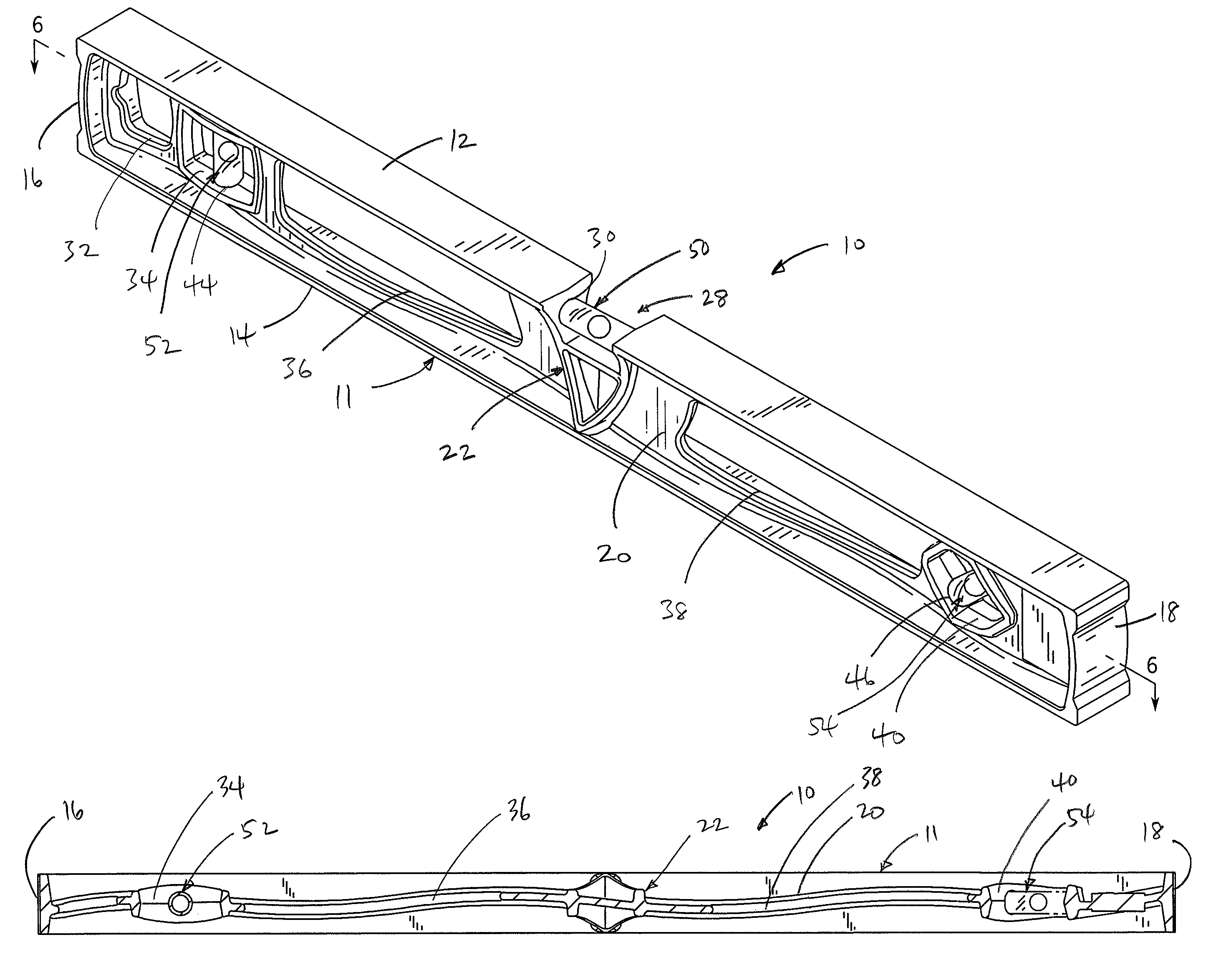
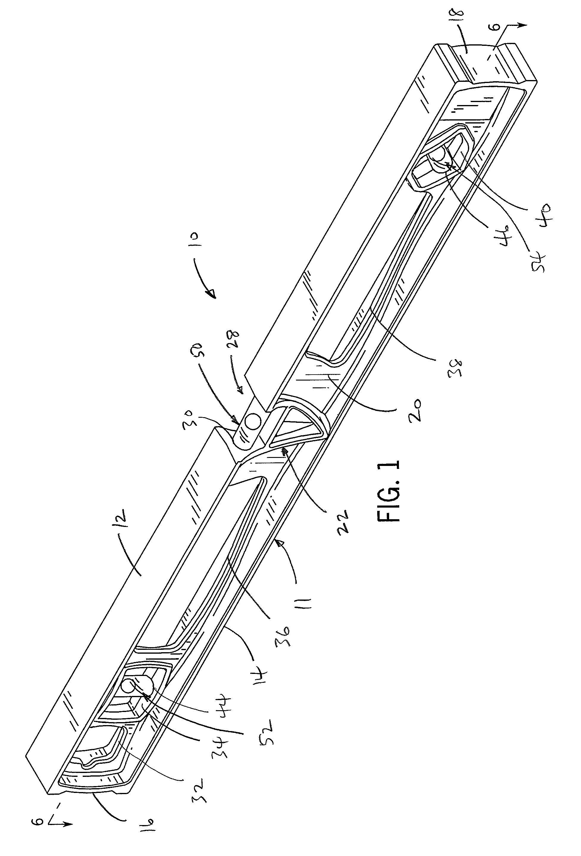
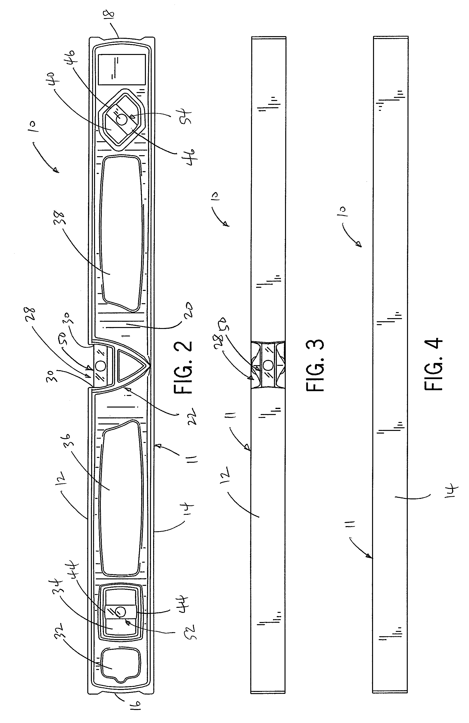
[0018]FIGS. 1-6 show a tool, such as a level 10, made in accordance with the invention. The level 10 includes a frame that is formed of an integral piece of molded material such as plastic or fiberglass, although it is understood that the level 10 may be formed of any other satisfactory material. The level 10 includes a frame 11 having a planar top flange 12 and a planar bottom flange 14, which extend parallel to each other between a pair of opposed end walls 16, 18. A web 20 extends between and interconnects the flanges 12, 14 and end walls 16, 18.

[0019]The level 10 has a generally I-shaped cross section. A curved V-shaped center reinforcement 22 is formed within the level 10. The center reinforcement 22 creates a gap 28 in the upper flange 12 and in the web 20. The center reinforcement 22 includes slots or recesses 30 which are configured to receive and engage the ends of a bubble vial 50, in a manner as is known.

[0020]As shown in FIGS. 1-2, the web 20 is formed with a series of a...

second embodiment

[0023]FIGS. 7-9 show a tool, such as a level 110, made in accordance with the present invention. Similar reference characters (increased by 100) are used in FIGS. 7-9 as in FIGS. 1-6 to denote similar components and features. The level 110 of this embodiment is longer than the level 10 of FIGS. 1-6. Because of the increased length of the level 110, the web 120 can have additional apertures without decreasing the strength of the level 110. Representatively, apertures 136a and 136b may be located between vials 50 and 52, and apertures 138a and 138b may be located between vials 50 and 54. An additional aperture 140 may be located between vial 52 and end wall 116, and an additional aperture 142 may be located between vial 54 and end wall 118.

[0024]While the present invention has been shown and described with respect to specific embodiments, it is understood that various alternative and modifications are possible and are contemplated a being within the scope of the present invention. For...


PUM


Abstract

A molded plastic yet structurally rigid tool, such as a level, with a web extending in a generally undulating configuration. The undulating configuration of the web acts to strengthen and make the level more rigid when compared to a level with a planar web. The undulating configuration of the web is substantially symmetrical about the centerline of the level over its entire length, but may also be arranged in a number of non-planar embodiments.

Description

FIELD OF THE INVENTION[0001]The present invention relates to a level, and more specifically to a web configuration for a level.BACKGROUND OF THE INVENTION[0002]Leveling and / or plumbing devices, generally referred to as levels, are frequently used in construction or other applications for marking or determining the level or plumb orientation of an object or surface. In many cases, levels are constructed of a material such as wood or metal. To reduce manufacturing costs, and / or to reduce weight, it is also known to construct levels using a moldable material such as fiberglass or plastic. A typical molded level includes a rectangular frame defining a pair of spaced flanges that form the gauging surfaces of the level, a pair of opposing end walls, and a web that interconnects the flanges and end walls. The web is formed with a number of openings within which the measuring or “bubble” vials of the level are mounted. The web may also include openings that act as hand holes to facilitate h...

Claims


Application Information

Patent Timeline
Patent Type & Authority Patents(United States)
IPC IPC(8): B43L13/20
CPCG01C9/24G01C9/26
Inventor STEFANKO, JOHN M.
Owner JOHNSON LEVEL & TOOL MFG
Why Eureka
Try Eureka