Tent and frame for automatic umbrella style canopy tent
a tent and umbrella technology, applied in the field of tents and tent frames, can solve the problems of inconvenient user, broken spreaders, injuring users, etc., and achieve the effect of convenient user pacing or closing the tent, convenient user pacing, and secure maintaining the pitched state of the ten
- Summary
- Abstract
- Description
- Claims
- Application Information
AI Technical Summary
Benefits of technology
Problems solved by technology
Method used
Image
Examples
first embodiment
[0052]FIG. 4 is an exploded perspective view illustrating important elements of a frame for automatic umbrella style canopy tents, according to the present invention. FIG. 5 is a perspective view illustrating the assembled frame of FIG. 4.
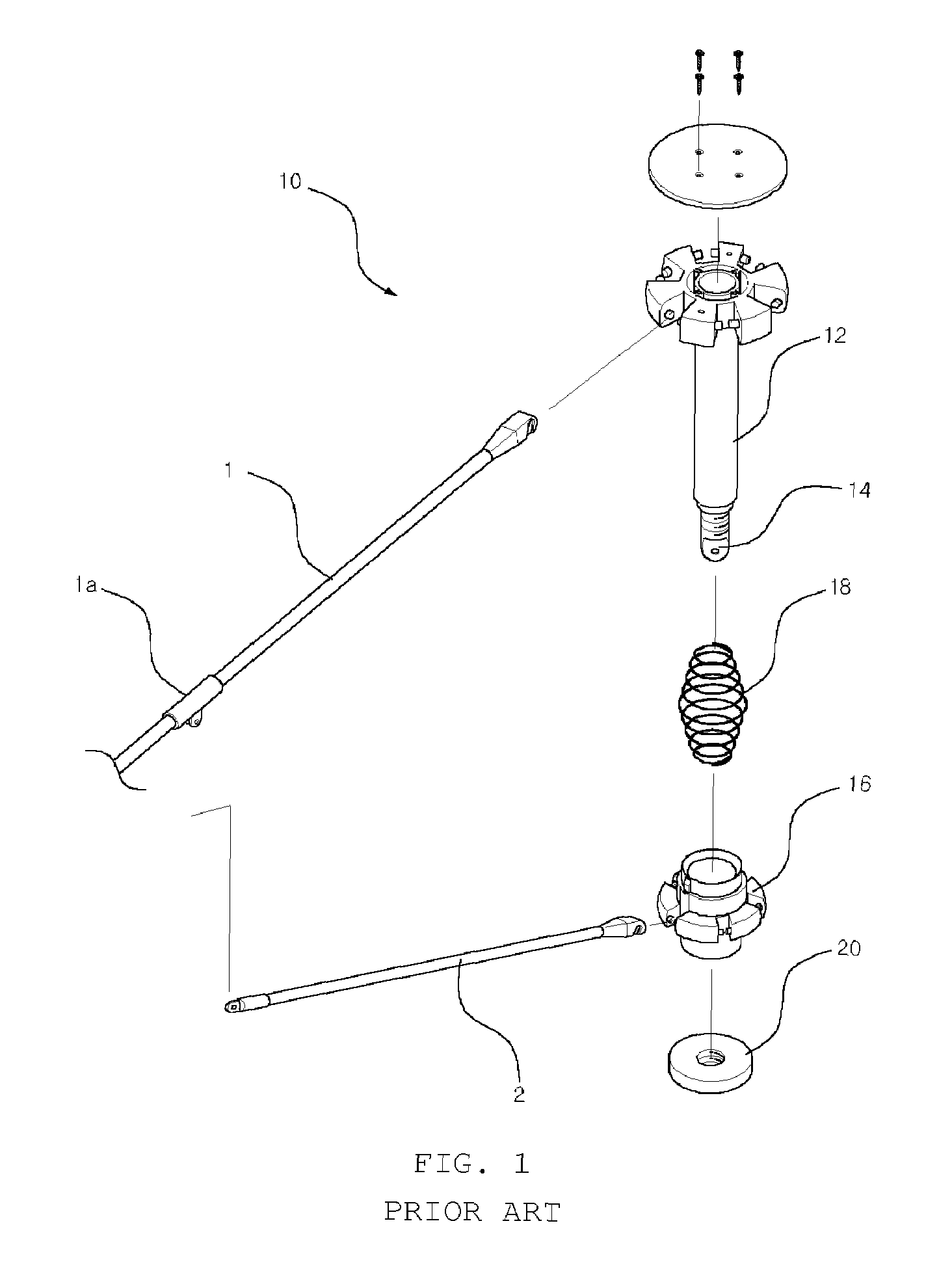
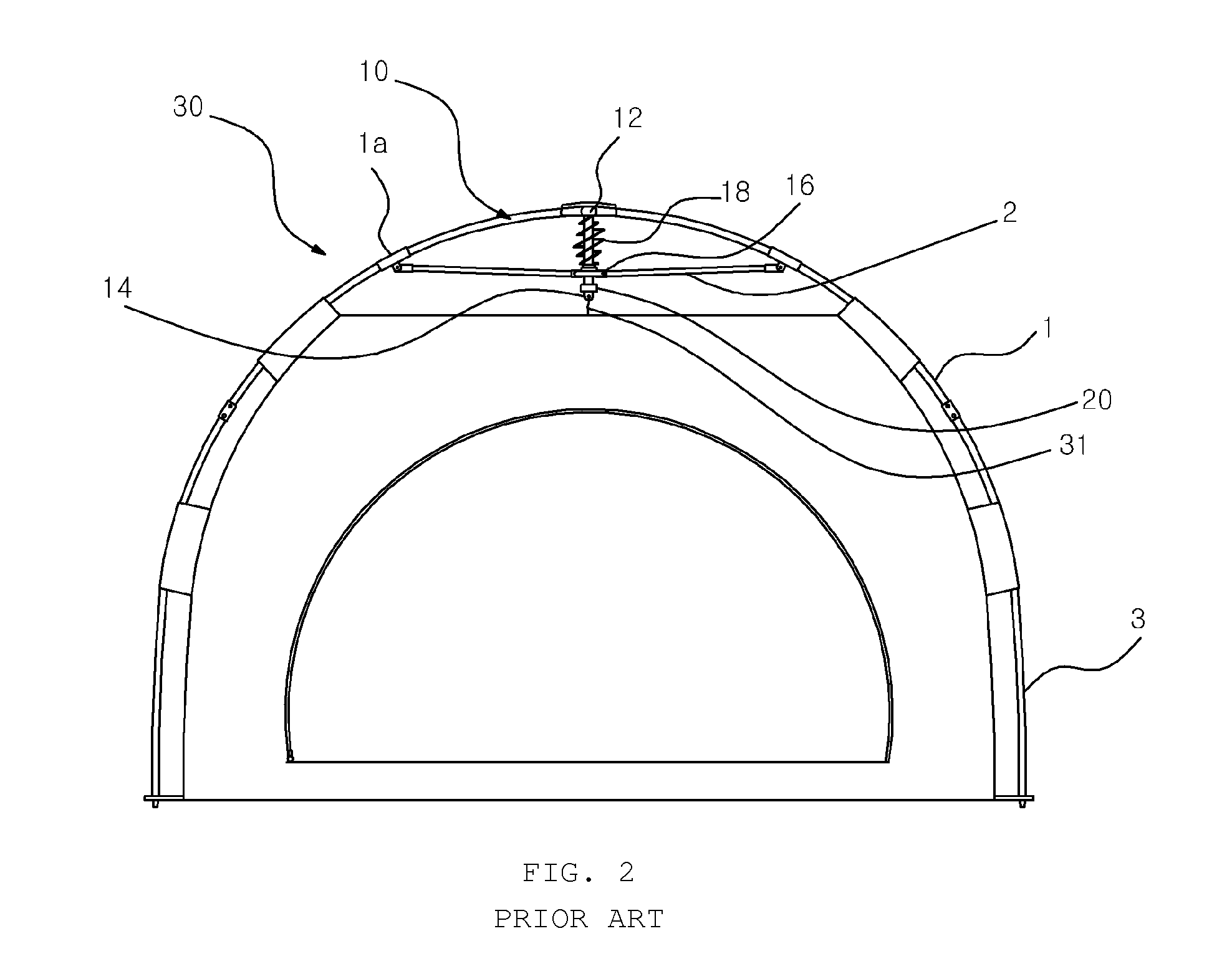
[0053]As shown in the drawings, the frame for automatic umbrella style canopy tents according to the first embodiment of the present invention comprises a rib holder 11, with a plurality of upper ribs 1 rotatably coupled to the rib holder 11 in radial directions. A connection member 12 is mounted to the rib holder 11. Further, a spreader holder 16 is movably fitted over a shank part of the connection member 12 such that the spreader holder 16 is movable upwards and downwards along the shank part of the connection member 12. A plurality of spreaders 2 is coupled at first ends thereof to the spreader holder 16 and coupled by hinge joints 1a at second ends thereof to the upper ribs 1, thus expanding or collapsing the upper ribs 1 in radial directions ...
second embodiment
[0076]Herein below, the present invention will be described with reference to the accompanying drawings.
[0077]FIG. 8 is an exploded perspective view illustrating the important elements of a frame for automatic umbrella style canopy tents, according to the second embodiment of the present invention. FIG. 9 is a perspective view illustrating the assembled frame of FIG. 8.
[0078]As shown in the drawings, the general shape of the frame for automatic umbrella style canopy tents according to the second embodiment of the present invention remains the same as that described for the first embodiment, but each of the spreaders 2 comprises a first spreader part 2a which is coupled to the hinge joint 1a of the upper rib 1, and a second spreader part 2b which is coupled to the spreader holder 16. The rear part 2d of the first spreader part 2a is configured such that the diameter of the rear part 2d is reduced compared to the diameter of the front part, while the second spreader part 2b is configu...
third embodiment
[0094]Herein below, the present invention will be described with reference to the accompanying drawings.
[0095]FIG. 12 is an exploded perspective view illustrating the important elements of a frame for automatic umbrella style canopy tents, according to the third embodiment of the present invention. FIG. 13 is a perspective view illustrating the assembled frame of FIG. 12.
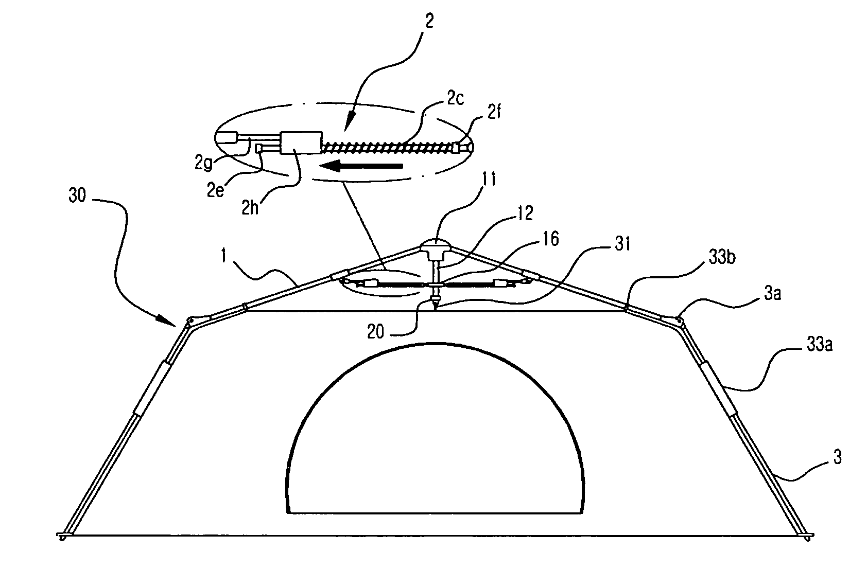
[0096]As shown in the drawings, the general shape of the frame for automatic umbrella style canopy tents according to the third embodiment of the present invention remains the same as that described for the first and second embodiments, but each of the spreaders 2 is configured as an integrated structure which comprises a front stopper 2e provided at the front end of the spreader 2 coupled to the hinge joint 1a of the upper rib 1, and a rear stopper 2f provided at the rear end of the spreader coupled to the spreader holder 16. A movable block 2h, which is integrated with a coupling rod 2g and coupled to the hinge jo...
PUM
 Abstract
Description
Claims
Application Information
 - R&D
- Intellectual Property
- Life Sciences
- Materials
- Tech Scout
- Unparalleled Data Quality
- Higher Quality Content
- 60% Fewer Hallucinations
Browse by: Latest US Patents, China's latest patents, Technical Efficacy Thesaurus, Application Domain, Technology Topic, Popular Technical Reports.
© 2025 PatSnap. All rights reserved.Legal|Privacy policy|Modern Slavery Act Transparency Statement|Sitemap|About US| Contact US: help@patsnap.com


