Wire cover assembly for vehicle interior mirror

a technology for interior mirrors and wire covers, which is applied in the direction of machine supports, instruments, other domestic objects, etc., can solve the problems of difficult to achieve wire routing through the support arm and requires particular mounting components

Inactive Publication Date: 2009-03-31
DONNELLY CORP
View PDF84 Cites 35 Cited by
  • Summary
  • Abstract
  • Description
  • Claims
  • Application Information

AI Technical Summary

Benefits of technology

[0007]The present invention provides an interior rearview mirror assembly which has a wire management system or wire cover assembly for covering and routing an electrical wire from generally at a rear portion of the mirror casing to generally at the vehicle headliner. The wire cover assembly may be readily assembled at the mirror assembly before the mirror assembly is installed in a vehicle and / or at the mirror assembly and windshield after the mirror assembly is installed in the vehicle.
[0010]An operator or operators at a vehicle assembly plant thus may mount the mirror assembly to an interior portion of the vehicle (such as to a mirror mounting button at an interior surface of the vehicle windshield), and may (or another operator may) readily route and contain / conceal the wires or wire harnesses between the mirror casing and the vehicle headliner via the wire cover or wire management system or assembly of the present invention. For example, the mounting base cover portion and support arm sleeve of the wire cover assembly may be provided to the vehicle assembly plant with the mirror assembly (such as a mirror unit having the mounting assembly and mounting base cover assembly and support arm sleeve assembled as a unit), and with the mirror wire routed along the support arm and within the support arm sleeve and along the mounting base and within the mounting base cover assembly. An operator or operators thus may readily install the mirror assembly and wire cover assembly unit in the vehicle and connect the vehicle wire harness to the mirror wire harness, and then may cover or conceal the vehicle wire harness via the channel member so that the vehicle wire harness is substantially contained or concealed between the mounting base cover portion and the vehicle headliner. Optionally, the wire cover assembly may be assembled at the mirror assembly and windshield after the mirror assembly is installed in the vehicle. For example, an operator may position the wires or wire harnesses at a generally desired location and may snap or readily position or otherwise mechanically attach the wire cover assembly components (including the mounting base cover assembly and support arm sleeve) to the mirror mounting assembly and / or other wire cover assembly components and / or the vehicle headliner to substantially route and contain the wires or wire harnesses along the wire cover assembly and substantially out of view of a person viewing the mirror assembly.
[0011]Therefore, the present invention provides an interior rearview mirror assembly which provides a wire cover or wire management assembly or system that substantially contains and / or conceals the mirror wire that extends from the mirror casing. The wire cover assembly allows for an operator at a vehicle assembly plant to readily electrically connect the vehicle wire to the mirror wire (which may provide power and control and / or communication signals between the mirror electronics and the vehicle) and to readily substantially cover and / or conceal or manage the wires without having to route or thread wires through and along passageways and the like. The wire cover assembly thus provides enhanced operator processing at a vehicle assembly plant and thus may provide reduced assembly time and costs.

Problems solved by technology

Although it is known to route a mirror wire extending from the mirror through a support arm of the mirror assembly, such as is described in U.S. Pat. No. 5,984,482, which is hereby incorporated herein by reference in its entirety, such routing of the wire through the support arm requires particular mounting components and may be difficult to accomplish.

Method used


Image

  • Wire cover assembly for vehicle interior mirror
  • Wire cover assembly for vehicle interior mirror
  • Wire cover assembly for vehicle interior mirror

Examples


Embodiment Construction

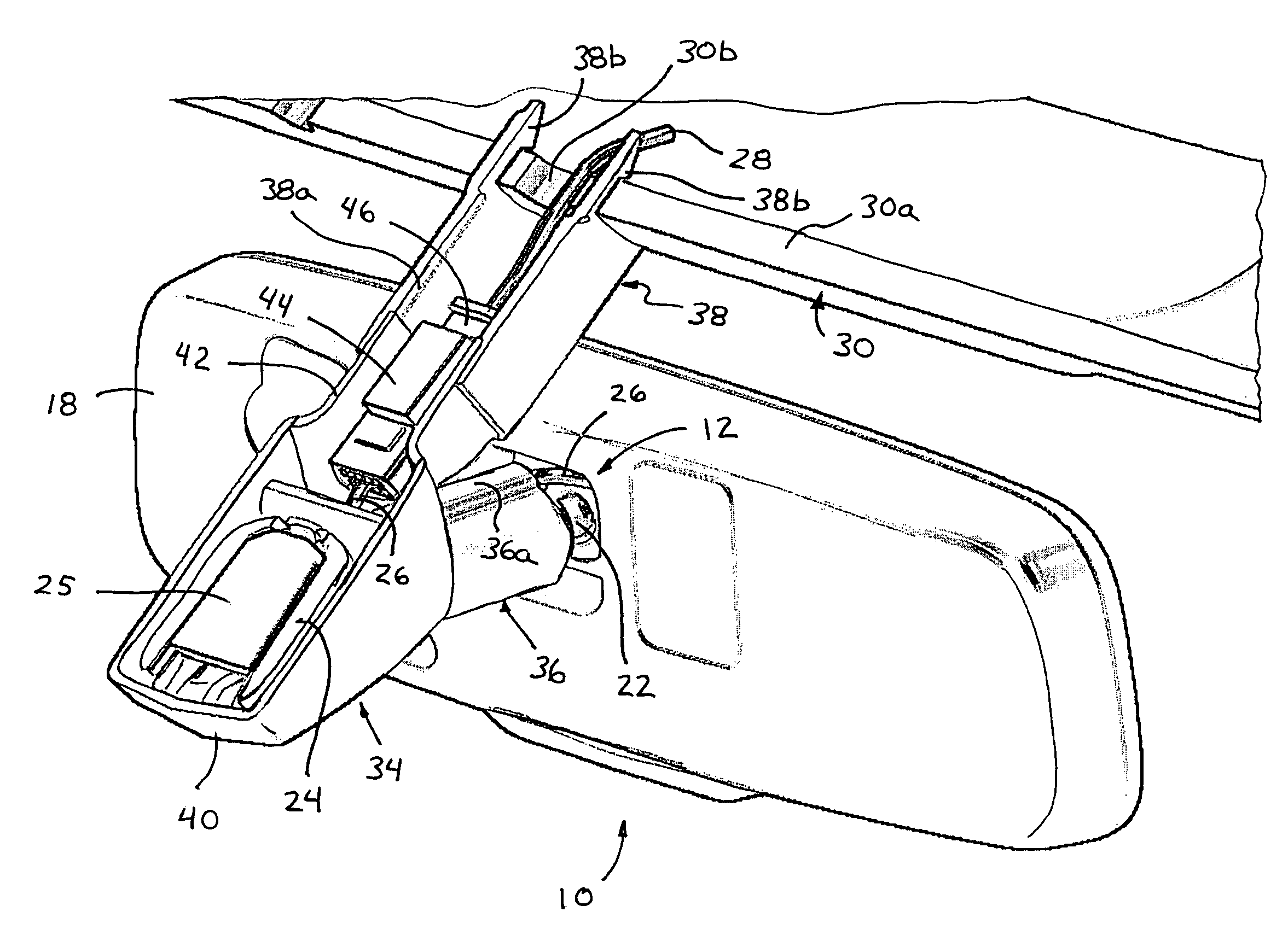
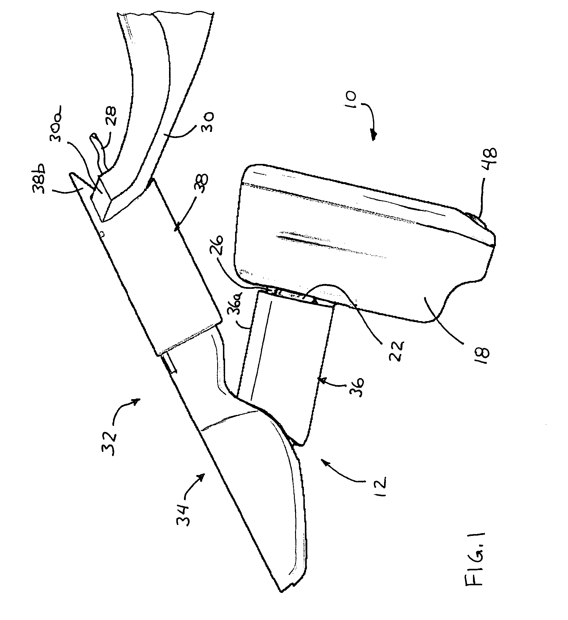
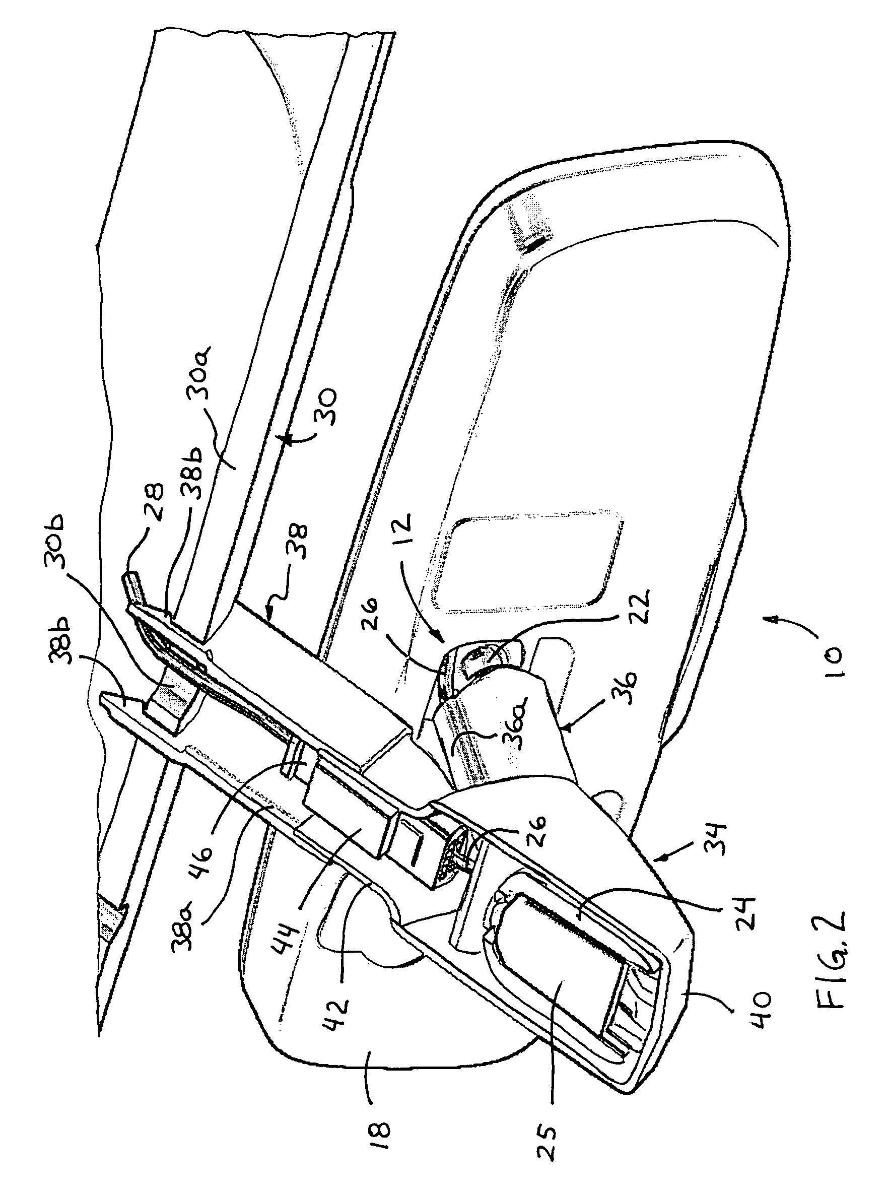
[0024]Referring now to the drawings and the illustrative embodiments depicted therein, an interior rearview mirror assembly 10 of a vehicle is pivotally or adjustably mounted to an interior portion of a vehicle, such as via a double ball mounting arrangement or assembly 12 (FIGS. 1, 2 and 6-11). Mirror assembly 10 includes a reflective element 17 (FIG. 11) and a polymeric-material housing or casing 18. The mounting or assembly 12 includes a support arm 22 and a mounting or base portion or channel mount 24, and adjustably mounts the mirror casing 18 and / or the reflective element 17 to an interior portion of the vehicle, such as to an interior surface of a windshield of the vehicle or the like. Mirror assembly 10 includes an electronic accessory or display or circuitry or circuit element 23 (FIG. 11) and an electrical wire or cable 26 (such as a multi-wire cable or ribbon cable or other suitable electrical conductor or link or the like) that extends from circuit element 23 (such as a ...


PUM


Abstract

An interior rearview mirror assembly for a vehicle includes a circuit element having a mirror wire harness extending therefrom and extending from a mirror casing. The mirror assembly includes a mirror mounting assembly having a mounting base and a support arm for adjustably mounting the mirror reflective element at the mounting base. The mirror wire harness is routed along an exterior surface of the support arm and an exterior surface of the mounting base. A support arm sleeve is attached at an exterior of the support arm and routes and may contain the mirror wire harness substantially along the support arm and within the support arm sleeve. A mounting base cover assembly is disposed at the mounting base of the mirror assembly and substantially conceals the mounting base and the mirror wire harness at the mounting base.

Description

CROSS REFERENCE TO RELATED APPLICATION[0001]The present application claims the benefit of U.S. provisional application Ser. No. 60 / 729,430, filed Oct. 21, 2005, which is hereby incorporated herein by reference in its entirety.FIELD OF THE INVENTION[0002]The present invention relates generally to the field of interior rearview mirror assemblies for vehicles and, more particularly, to interior rearview mirror assemblies which incorporate an accessory or feature, particularly an electronic accessory or feature.BACKGROUND OF THE INVENTION[0003]Mounting arrangements or assemblies for mounting an interior rearview mirror assembly to an interior portion of a vehicle typically include a mounting arm that is pivotally attached to the mirror assembly and / or to a channel mount or mounting base, which in turn mounts to the interior portion of the vehicle. For example, a typical mounting assembly may include a mounting arm with a ball member or spherical member or portion at each end, with one e...

Claims


Application Information

Patent Timeline
Patent Type & Authority Patents(United States)
IPC IPC(8): G02B7/182
CPCB60R1/04
Inventor HOOK, RICHARD R.
Owner DONNELLY CORP
Why Eureka
Try Eureka