Thermal processor with contaminant removal cartridge

a technology of contaminant removal and thermal processor, which is applied in the direction of separation processes, instruments, photosensitive materials, etc., can solve the problems of affecting the expected life of the contaminant removal cartridge, and affecting the effect of thermal processing

Inactive Publication Date: 2009-03-31
CARESTREAM HEALTH INC
View PDF18 Cites 6 Cited by
  • Summary
  • Abstract
  • Description
  • Claims
  • Application Information

AI Technical Summary

Benefits of technology

[0011]During operation of the thermal processor, substantially all condensable and all odor-causing gaseous contaminants produced by the imaging media during thermal development are collected and / or absorbed within the contaminant removal cartridge. Additionally, since the temperature of the first air flow is substantially at the processing temperature of the oven, condensation of gaseous contaminants within the oven or other internal components of processor 30 is substantially eliminated.
[0012]When the contaminant removal cartridge needs to be replaced, a user of the thermal processor is able to simply remove and replace the “used” contaminant removal cartridge with a “fresh” contaminant removal cartridge. Since collection of the gaseous contaminants is substantially confined to the user-replaceable contaminant removal cartridge, costly maintenance and downtime associated with cleaning condensed gaseous contaminants from within the thermal processor is substantially reduced. Furthermore, because substantially all of the condensable portion of the gaseous contaminants is collected in the heat exchanger, the effectiveness of the absorbent material is extended, thereby extending an expected life of the contaminant removal cartridge.

Problems solved by technology

These deposits can accumulate over time and can damage processor components, cause film jams within the processor, and cause visual defects in the developed image.
Due to its distance from the processing chamber, contaminants often condense and accumulate within the duct system.
Such maintenance can be costly and result in processor downtime.

Method used


Image

  • Thermal processor with contaminant removal cartridge
  • Thermal processor with contaminant removal cartridge
  • Thermal processor with contaminant removal cartridge

Examples


Embodiment Construction

[0019]The following is a detailed description of the preferred embodiments of the invention, reference being made to the drawings in which the same reference numerals identify the same elements of structure in each of the several figures.

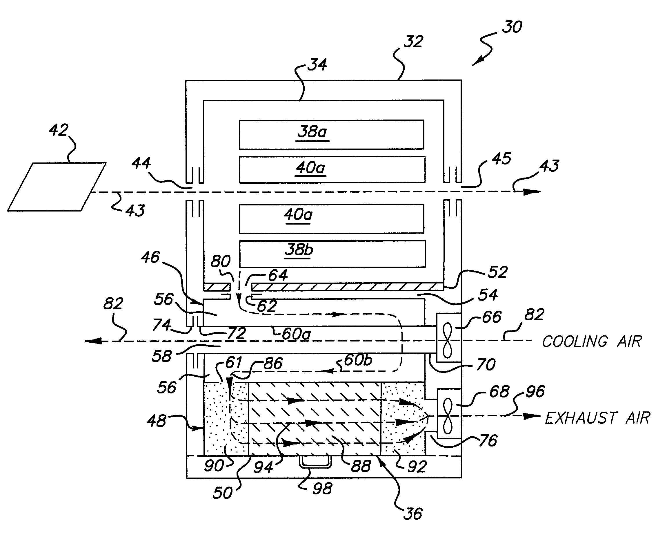
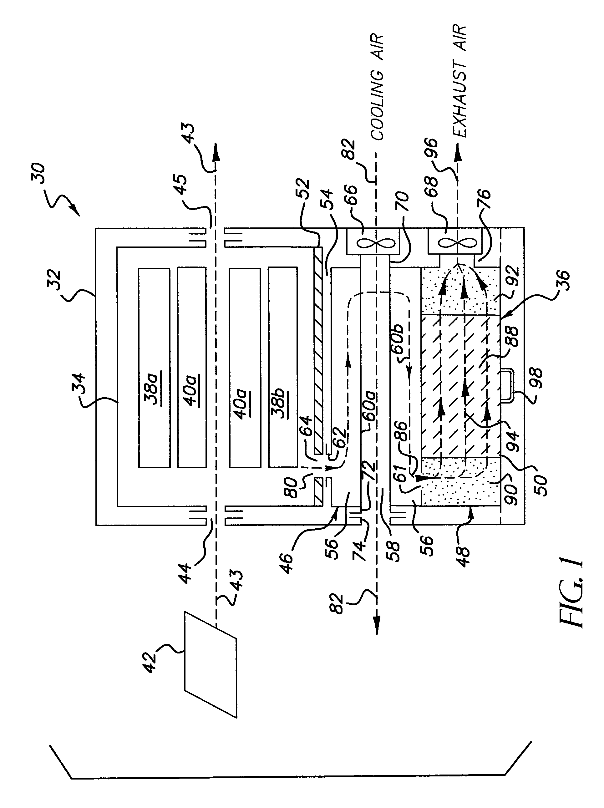
[0020]FIG. 1 is a block diagram illustrating generally one embodiment of a thermal processor 30 including a user replaceable contaminant removal cartridge in accordance with the present invention. Thermal processor 30 includes an enclosure 32, an oven 34, and a contaminant removal cartridge 36 according to one embodiment of the present invention. Oven 34 includes a heat source 38 and a transport system 40. In operation, transport system 40 receives and transports exposed photothermographic media 42 through oven 34 along a transport path 43 from an entrance 44 to an exit 45. Heat source 38 heats imaging media 42 to at least a desired processing temperature to thermally develop the exposed image as it moves along transport path 44. As imaging media 42...


PUM

PropertyMeasurementUnit
temperatureaaaaaaaaaa

Abstract

A thermal processor includes an oven for thermally developing an imaging media which produces gaseous contaminants during development. The gaseous contaminants includes odorous portions and condensable portions which have a condensation temperature. A contaminant removal cartridge has a housing configured to couple to the oven, a heat exchanger, and a filter module. The heat exchanger receives from the oven at least a first air flow at a first temperature, wherein the first temperature is above the condensation temperature, and including gaseous contaminants. The heat exchanger cools the first air flow to a desired filtering temperature, which is below the condensation temperature, to condense and collect the condensable portion of the gaseous contaminants and form a filtering air flow. The filter module receives the filtering air flow, to collect the remaining condensed contaminants, and to absorb the odorous portion of the gaseous contaminants to form an exhaust air flow.

Description

FIELD OF THE INVENTION[0001]The present invention relates generally to an apparatus and method for thermally processing an imaging media, and more specifically to an apparatus and method for thermally developing an imaging media employing a contaminant removal cartridge to collect airborne contaminants produced by the development process.BACKGROUND OF THE INVENTION[0002]Photothermographic film generally includes a base material, such as a thin polymer or paper, typically coated on one side with an emulsion of heat sensitive materials, such as dry silver. Once the film has been subjected to photo-stimulation, such as by light from a laser of a laser imaging system, for example, the resulting latent image is developed through application of heat to the film to form a visible image.[0003]Several types of processing machines have been developed for developing photothermographic film. One type employs a rotating heated drum having multiple pressure rollers positioned around the drum's ci...

Claims


Application Information

Patent Timeline
Patent Type & Authority Patents(United States)
IPC IPC(8): G03D7/00
CPCG03D7/00G03C1/49881G03C2200/09
Inventor STRUBLE, KENT R.MCDANIEL, DAVID J.NUTTER, JOHN M.
Owner CARESTREAM HEALTH INC
Why Eureka
Try Eureka