Emergency electric power supply unit

a technology of emergency power supply and electric power supply, which is applied in the direction of emergency power supply arrangement, electric generator control, electric devices, etc., can solve problems such as secondary failure, and achieve the effect of preventing the occurrence of further accidents or the lik

Inactive Publication Date: 2009-03-31
ASHITATE ELECTRIC +1
View PDF11 Cites 2 Cited by
  • Summary
  • Abstract
  • Description
  • Claims
  • Application Information

AI Technical Summary

Benefits of technology

[0008]According to the present invention, when a failure is caused with a main electric power supply system, electric power is supplied to auxiliary machineries by an emergency controlling circuit and the auxiliary machineries are controlled in response to the operational states of industrial apparatus at the time of the malfunction of the main electric power supply system, thereby the secondary failure can be prevented and in consequence, the occurrence of further accident or the like can be prevented.

Problems solved by technology

However, with regard to such conventional system, even though the electric power is supplied by changing over to the auxiliary electric power supply from the main electric power supply when the main battery is failed at the time of the accident of the vehicle, there was a possibility that a secondary failure may be caused because the responsive operational control of the vehicle was not performed at the time of the malfunction of this main electric power supply.

Method used


Image

  • Emergency electric power supply unit
  • Emergency electric power supply unit
  • Emergency electric power supply unit

Examples


embodiment 1

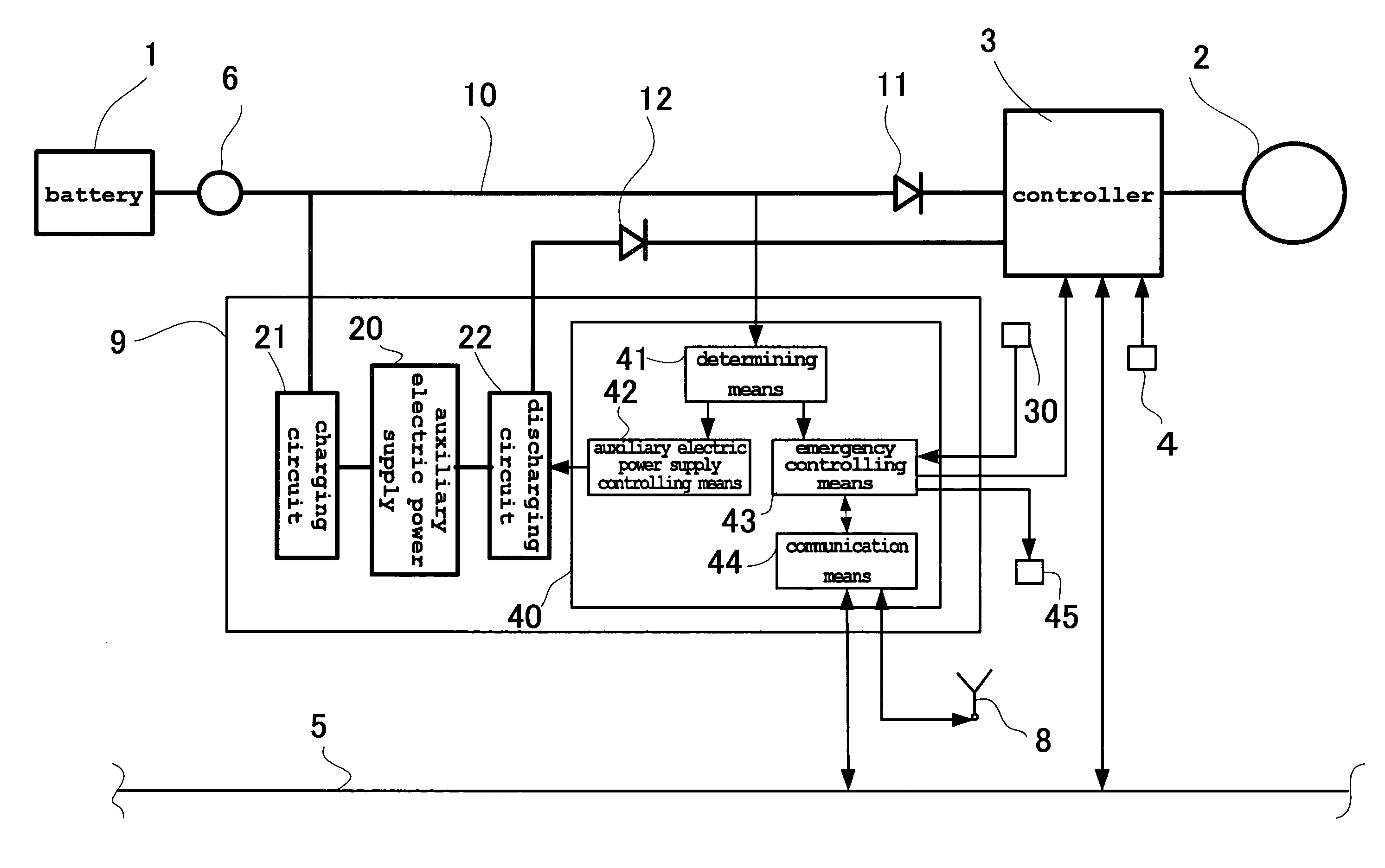
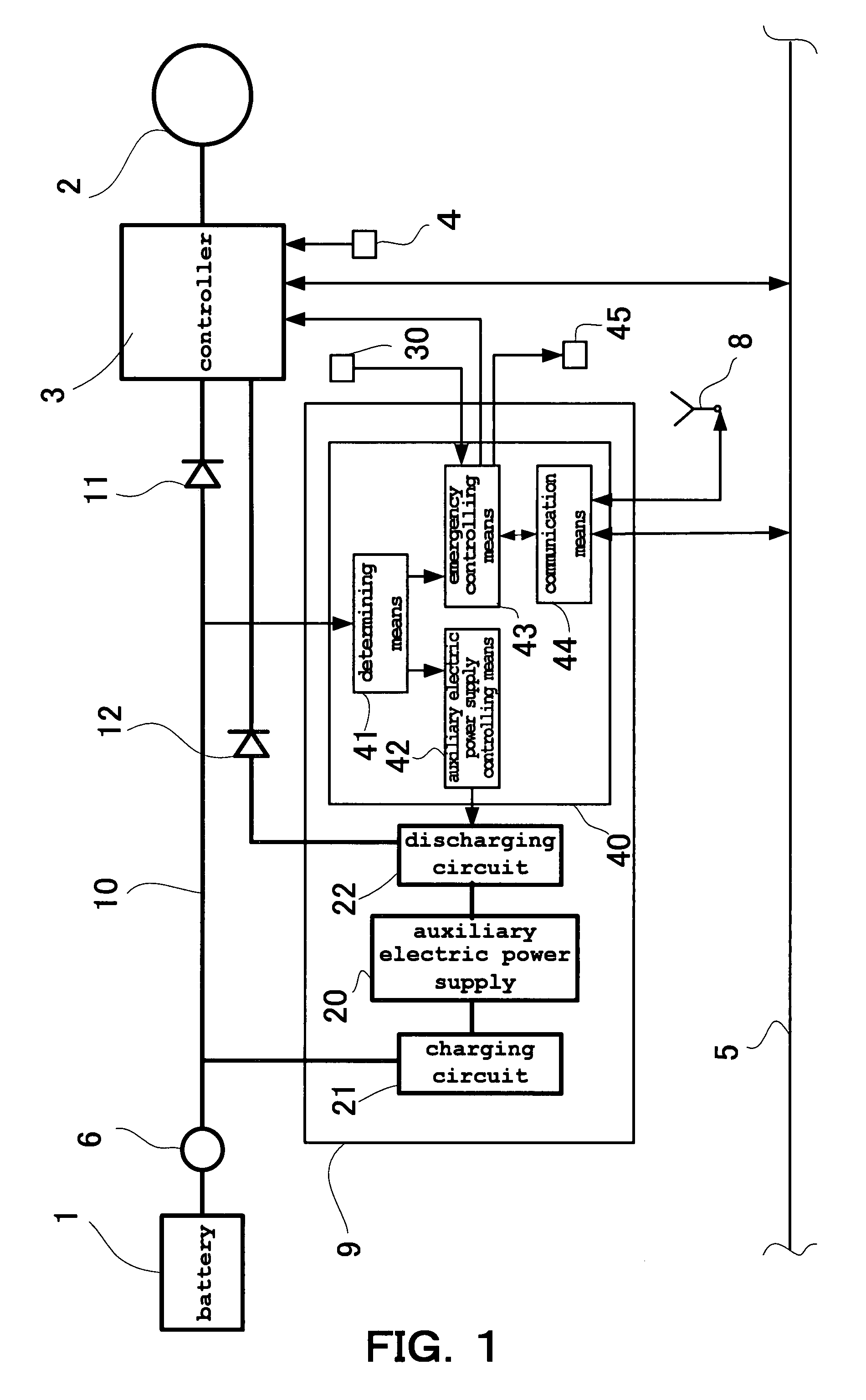
[0013]A description is given to the emergency electric power supply unit according to the embodiment 1 of the present invention with reference to FIG. 1. FIG. 1 is a block diagram showing the construction that the emergency electric power supply unit according to the present embodiment 1 is applied to a power steering unit of a vehicle.

[0014]The power steering unit is that mounted on the vehicle serving as the industrial apparatus, and comprises a battery 1 serving as a main electric power supply, a main electric power supply circuit 10 connected to the battery 1 through an ignition switch 6, an assisting motor 2 which is driven by the electric power supplied from the battery 1 to provide assisting force to a steering shaft (not illustrated), a controller 3 for controlling the operation of the assisting motor 2, and an emergency electric power supply unit 9 activated at the time of the malfunction of the main electric power supply system constructed from the battery 1 and the main e...

embodiment 2

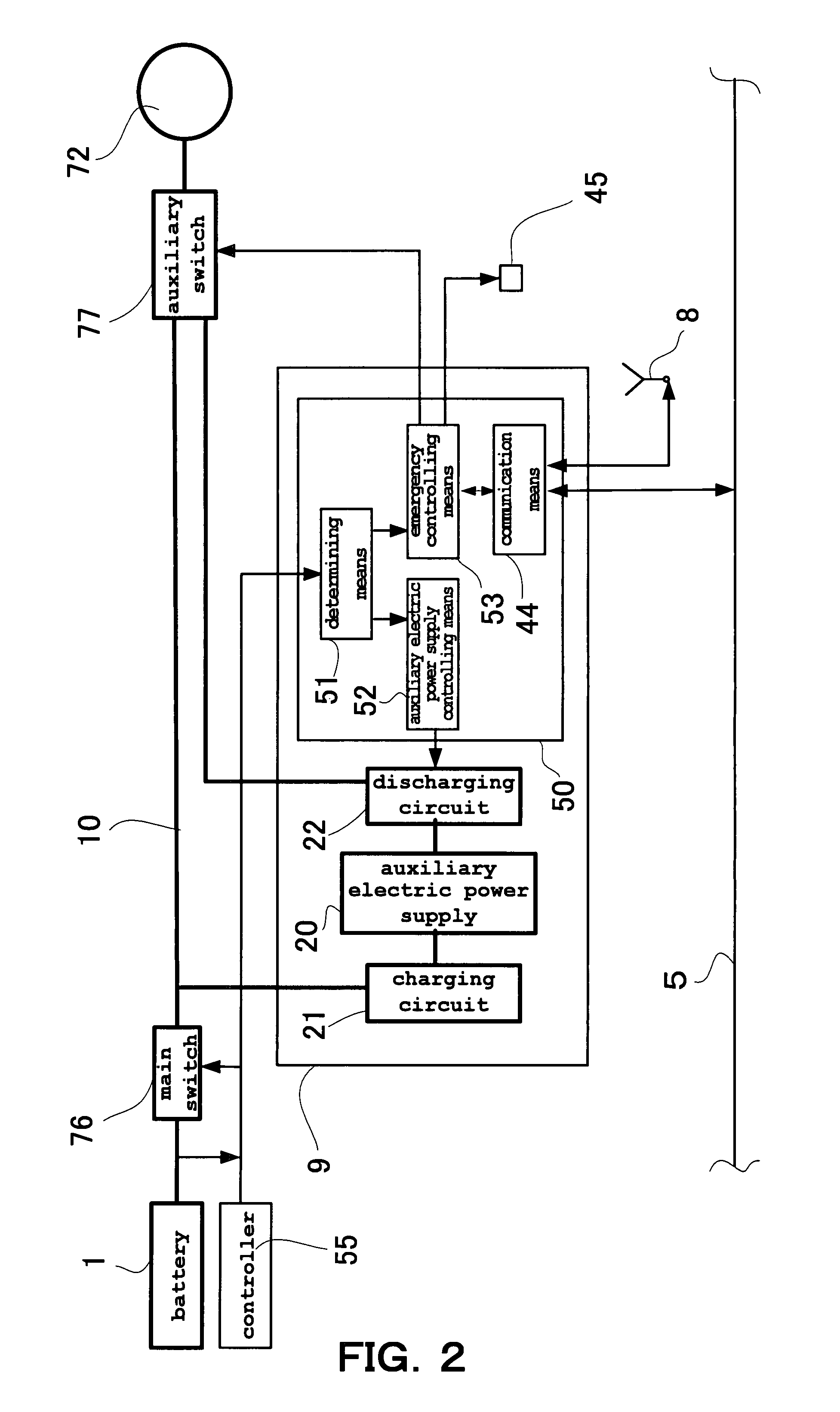
[0039]A description is given to the emergency electric power supply unit according to the embodiment 2 of the present invention with reference to FIG. 2. FIG. 2 is a block diagram showing the construction that the emergency electric power supply unit according to the present embodiment 2 is applied to a rear position lamp unit of a vehicle. In addition, the identical numerical figures are designated and detailed descriptions are omitted for the same constructions as in the above described embodiment 1.

[0040]The rear position lamp unit is that mounted on the vehicle serving as the industrial apparatus, and comprises a battery 1 serving as the main electric power supply, a main electric power supply circuit 10 connected to the battery 1, a main switch 76 and an auxiliary switch 77 interveningly provided in series to the main electric power supply circuit 10, a rear position lamp 72 provided at the rear of the vehicle and operated by the main switch 76 and the auxiliary switch 77, a co...

embodiment 3

[0052]A description is given to the emergency electric power supply unit according to the embodiment 3 of the present invention with reference to FIG. 3. FIG. 3 is a block diagram showing the construction that the emergency electric power supply unit according to the present embodiment 3 is applied to an industrial plant. In addition, the identical numerical figures are designated and detailed descriptions are omitted for the same constructions as in the above described embodiment 1.

[0053]Industrial plants into which the emergency electric power supply unit according to the present embodiment 3 is applied include industrial apparatus of chemical plants, electric power plants, production lines or the like which are those operated by cooperatively controlling a plurality of auxiliary machineries such as motors, fans, heat treat furnaces, electric operated valves or the like in accordance with commands from a control center.

[0054]The industrial plant comprises a main electric power sup...


PUM


Abstract

An emergency electric power supply unit (9) for backing up the main electric power supply system (1, 10) at the time of the malfunction of the main electric power supply system (1, 10) which includes an industrial apparatus operated by cooperatively controlling an auxiliary machinery (2) operated by the electric power supplied from the main electric power supply system (1, 10), an auxiliary electric power supply (20) for storing the electric power, a charging circuit (21) for charging the electric power supplied from the main electric power supply (1) in the auxiliary electric power supply (20), a discharging circuit (22) for supplying the electric power charged in the auxiliary electric power supply (20) to the auxiliary machinery (2), and an emergency controlling circuit (40) for controlling the discharging circuit (22) so that the electric power from the auxiliary electric power supply (20) is supplied to the auxiliary machinery (2) at the time of the malfunction of the main electric power supply system (1, 10) and for controlling the operation of the auxiliary machinery (2) in response to the operational state of the industrial apparatus at the time of the malfunction of the main electric power supply system (1, 10).

Description

FIELD OF THE INVENTION[0001]The present invention relates to an emergency electric power supply unit.BACKGROUND OF THE INVENTION[0002]In recent years, engines, transmissions, brakes, steering or the like have been progressively controlled electronically in motor vehicles, and a cooperative control is performed by trans-communicating information between respective controllers through communication circuits.[0003]However, with the motor vehicle installed with such electronic control units, there is a possibility that the entire electronic control units become non-operatable when a failure of the main battery is caused at the time of an accident of the vehicle or the like.[0004]An emergency notifying system which is installed on a vehicle that changes over a supply of electrical power to an auxiliary battery when the main battery is failed at the time of an accident or the like is disclosed in JP2000-278885.SUMMARY OF THE INVENTION[0005]However, with regard to such conventional system,...

Claims


Application Information

Patent Timeline
Patent Type & Authority Patents(United States)
IPC IPC(8): H02P9/00
CPCB60R16/03B60Q1/52H01H2300/018
Inventor OZAWA, TADAHIKOTORII, TETSUOASHITATE, NORIOSAGARA, IWAO
Owner ASHITATE ELECTRIC
Why Eureka
Try Eureka