
Method and apparatus for a frequency diverse array

Inactive Publication Date: 2009-03-31
THE UNITED STATES OF AMERICA AS REPRESETNED BY THE SEC OF THE AIR FORCE
View PDF14 Cites 8 Cited by
  • Summary
  • Abstract
  • Description
  • Claims
  • Application Information

AI Technical Summary

Benefits of technology

This solution allows for range-dependent beamforming, reducing interference from fixed angles and enabling simultaneous operations like spotlight and strip map synthetic aperture radar, as well as combining radar and communications signals, overcoming the limitations of conventional synthetic aperture radar by varying the antenna beam pattern with range.

Problems solved by technology

A limitation of the prior art is that, for any instant of time, beam steering is fixed in angle for all ranges.

Method used


Image

  • Method and apparatus for a frequency diverse array
  • Method and apparatus for a frequency diverse array
  • Method and apparatus for a frequency diverse array

Examples


Embodiment Construction

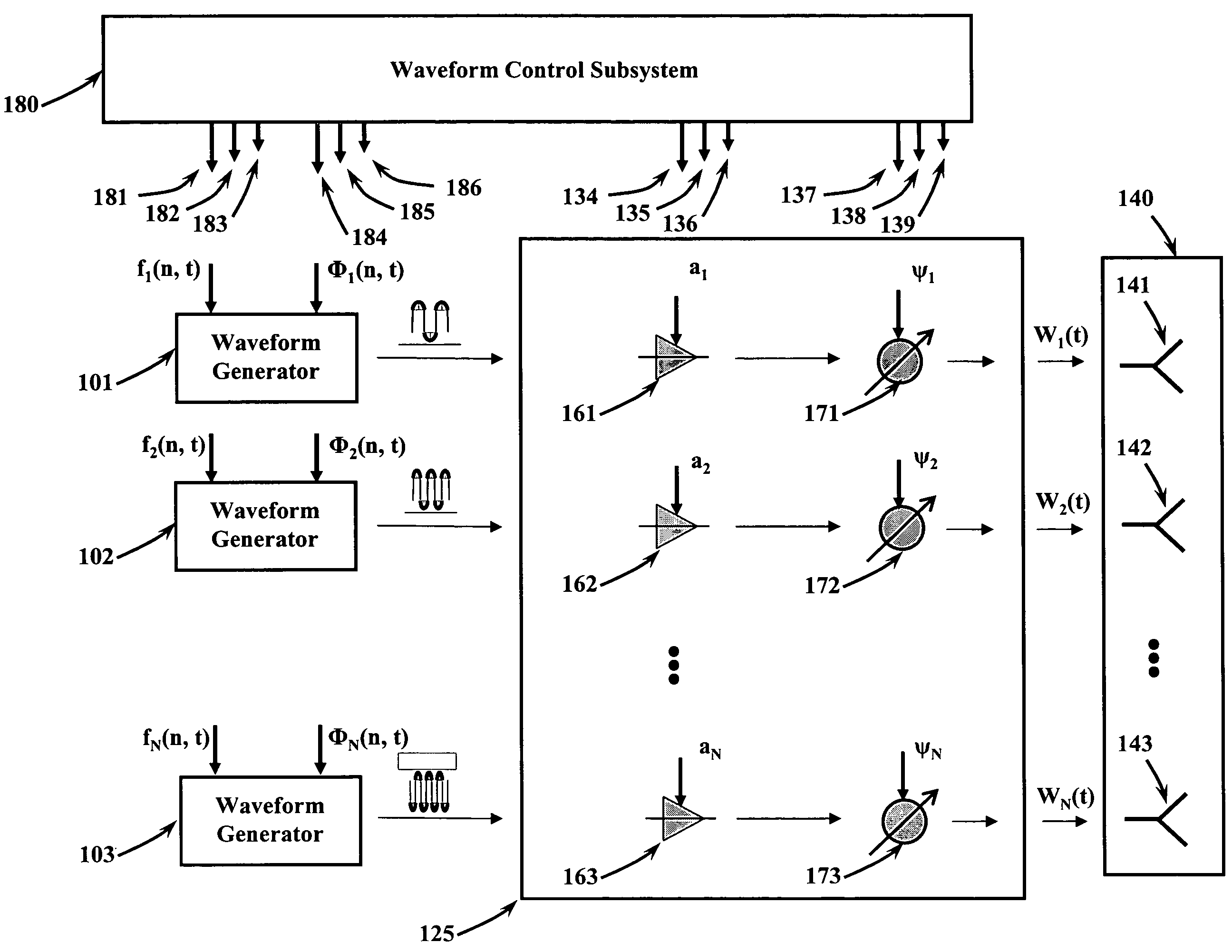
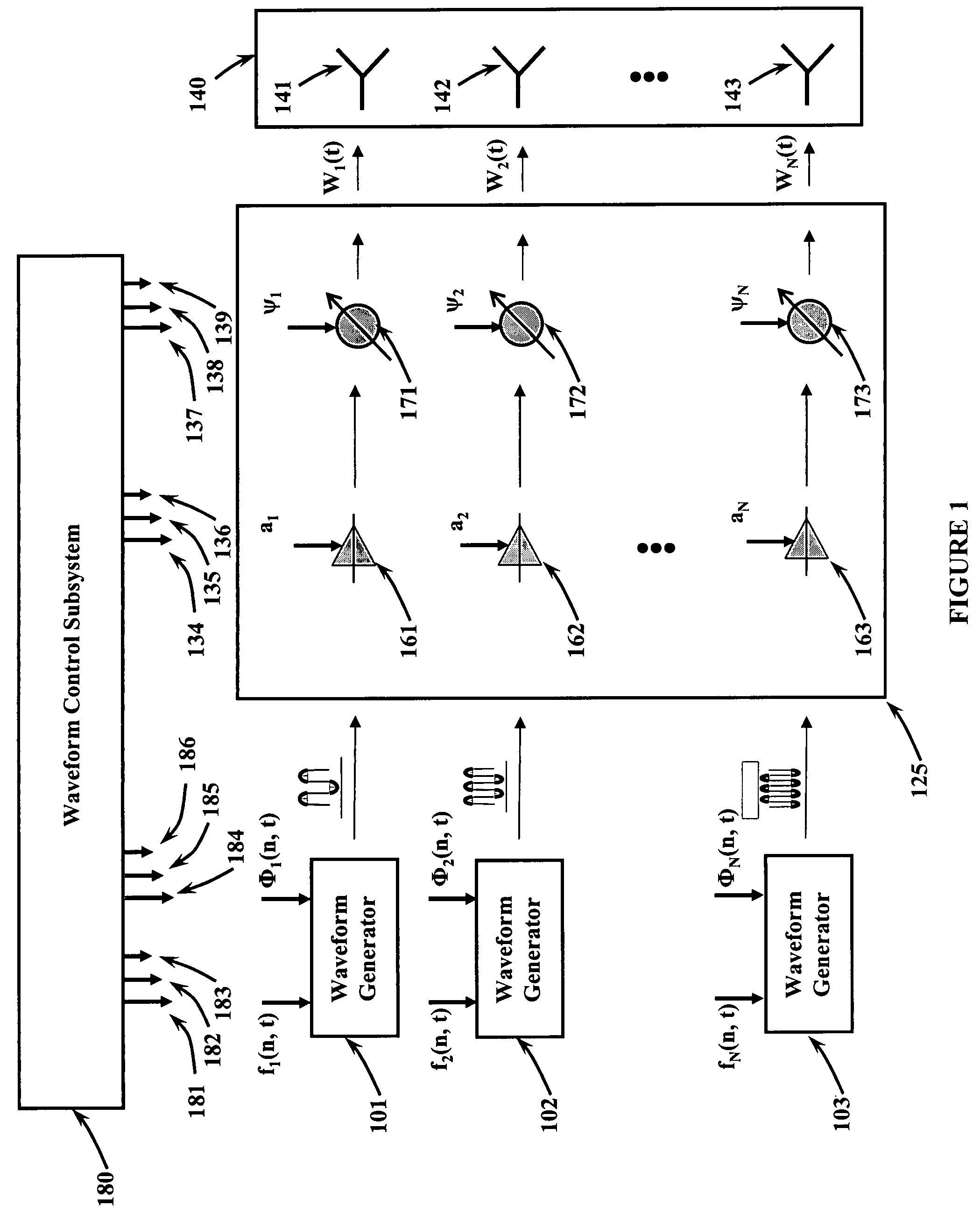
[0030]Referring to FIG. 1, depicts how the present invention provides enhanced control over the synthesis of transmitted signals. A plurality of waveform generators 101, 102 through 103 output radio frequency signals which are provided to a transmit / receive module 125. The outputs of the transmit / receive module 125 are provided to a like plurality of antenna radiating / receiving elements 141, 142 through 143. A waveform control subsystem 180 provides frequency modulation control signals 181, 182, 183 and phase modulation control signals 184, 185, 186 to the waveform generators 101, 102 through 103. The frequency and phase modulation control signals provide pulse-to-pulse and element-to-element frequency and phase diversity to the waveform generators as a function of time. The waveform control subsystem 180 also provides amplitude control signals 134, 135, 136 for power control and antenna weighting, and first phase control signals 137, 138, 139 for nominal beam steering. The frequenc...


PUM


Abstract

Method and apparatus for a frequency diverse array. Radio frequency signals are generated by a plurality of independent waveform generators and simultaneously applied to a transmit / receive module. A progressive frequency shift is applied to all radio frequency signals across all spatial channels. Amplitude weighting signals are applied for sidelobe control. Phase control is included for channel compensation and to provide nominal beam steering. The progressive frequency offsets generate a new term which cause the antenna beam to focus in different directions as a function of range.

Description

CROSS-REFERENCE TO RELATED APPLICATIONS[0001]The present application is a divisional application of and claims priority from related, and commonly assigned U.S. patent application Ser. No. 11 / 312,805 filed on Dec. 20, 2005, now U.S. Pat. No. 7,319,427 entitled “Method and Apparatus for a Frequency Diverse Array” also by Michael C. Wicks and Paul Antonik. Accordingly, U.S. patent application Ser. No. 11 / 312,805 is herein incorporated by reference.STATEMENT OF GOVERNMENT INTEREST[0002]The invention described herein may be manufactured and used by or for the Government for governmental purposes without the payment of any royalty thereon.BACKGROUND OF THE INVENTION[0003]This invention relates generally to the field of electronically-scanned phased array antennas. More specifically, the present invention relates to electronic beamformers for such antennas.[0004]Phased array antennas have been developed to provide electronic beam steering of radiated or received electromagnetic signals. I...

Claims


Application Information

Patent Timeline
Patent Type & Authority Patents(United States)
IPC IPC(8): H01Q3/00G01S13/32G01S13/536
CPCH01Q3/22
Inventor WICKS, MICHAEL C.ANTONIK, PAUL
Owner THE UNITED STATES OF AMERICA AS REPRESETNED BY THE SEC OF THE AIR FORCE
Learn More