High-resolution micro-lens 3D display with shared sub-pixel color signals

a micro-lens, color signal technology, applied in the direction of instruments, static indicating devices, optical elements, etc., can solve the problems of visual perception, undesirable pattern composed of small dots, and appearance in the imag

Active Publication Date: 2009-03-31
SONY CORP +1
View PDF30 Cites 11 Cited by
  • Summary
  • Abstract
  • Description
  • Claims
  • Application Information

AI Technical Summary

Problems solved by technology

This unequal resolution in the x and y directions negatively impacts visual perception and causes an undesirable pattern composed of small dots (optical moiré) to appear in the image.

Method used


Image

  • High-resolution micro-lens 3D display with shared sub-pixel color signals
  • High-resolution micro-lens 3D display with shared sub-pixel color signals
  • High-resolution micro-lens 3D display with shared sub-pixel color signals

Examples


Embodiment Construction

[0025]In the following detailed description of embodiments of the invention, reference is made to the accompanying drawings in which like references indicate similar elements, and in which is shown, by way of illustration, specific embodiments in which the invention may be practiced. These embodiments are described in sufficient detail to enable those skilled in the art to practice the invention, and it is to be understood that other embodiments may be utilized and that logical, mechanical, electrical, functional and other changes may be made without departing from the scope of the present invention. The following detailed description is, therefore, not to be taken in a limiting sense, and the scope of the present invention is defined only by the appended claims.

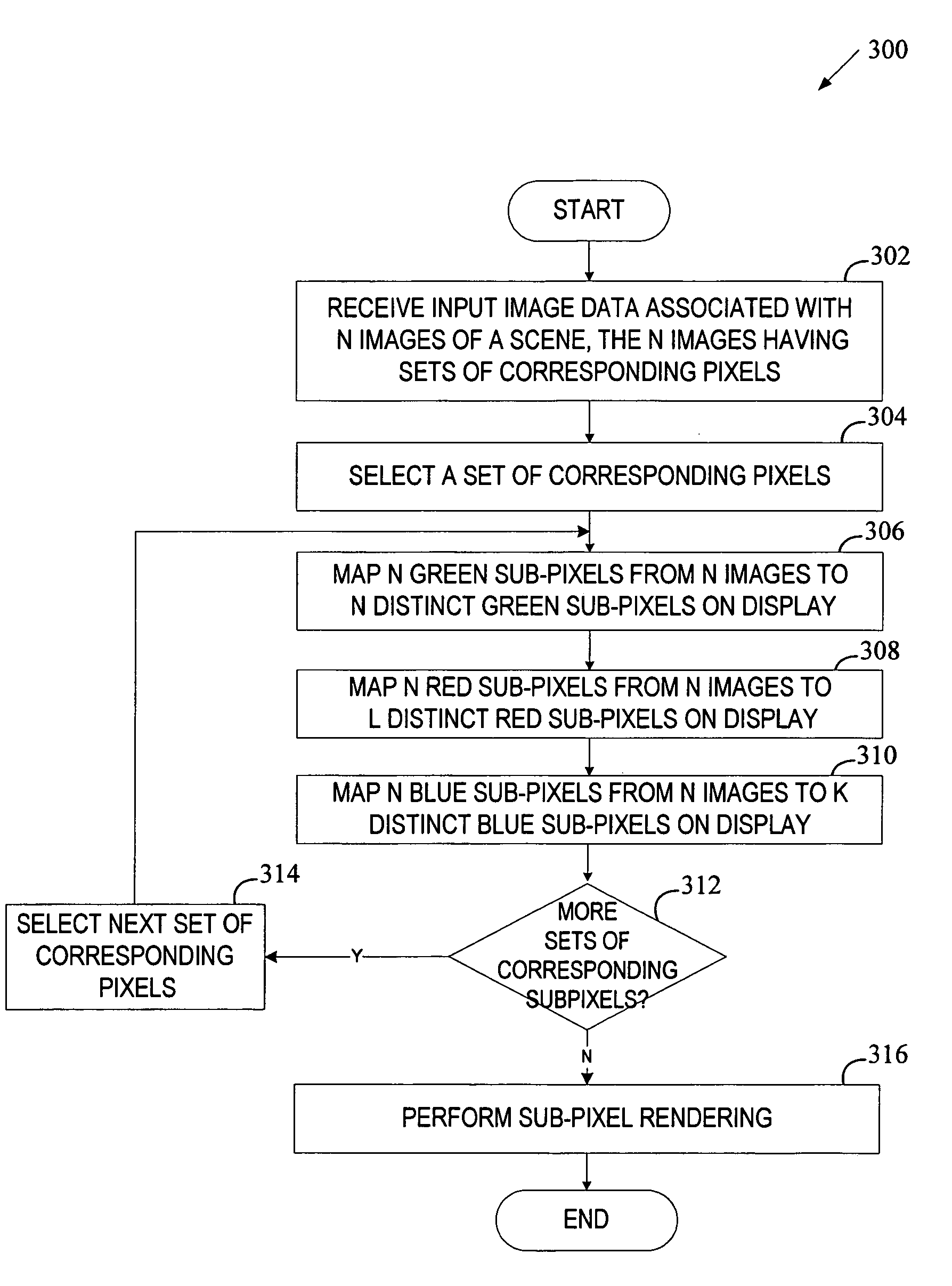
[0026]Beginning with an overview of the operation of the invention, FIG. 2 illustrates one embodiment of a 3D color display system 200. The system 100 receives images of a scene from multiple cameras 200. A scene may include...


PUM


Abstract

In one embodiment, a sub-pixel rendering method includes receiving 3D image data associated with pixel intensity values of N two-dimensional images having multiple sets of corresponding pixels. Each set of corresponding pixels includes N pixels (one pixel from each of N images) and each pixel has a green sub-pixel, a red sub-pixel and a blue sub-pixel. The method further includes mapping, for each selected set, N green sub-pixels, N red sub-pixels and N blue sub-pixels to M sub-pixels on a display to form a stereogram of the scene. The above mapping includes mapping N green sub-pixels from N images to N green sub-pixels on the display, mapping N red sub-pixels from N images to L red sub-pixels on the display, and mapping N blue sub-pixels from N images to K blue sub-pixels on the display, where L does not exceed N and K is lower than N.

Description

FIELD OF THE INVENTION[0001]The invention relates to three-dimensional color displays. More particularly, the invention relates to three-dimensional color displays with shared sub-pixel color signals.COPYRIGHT NOTICE / PERMISSION[0002]A portion of the disclosure of this patent document contains material which is subject to copyright protection. The copyright owner has no objection to the facsimile reproduction by anyone of the patent document or the patent disclosure as it appears in the Patent and Trademark Office patent file or records, but otherwise reserves all copyright rights whatsoever. The following notice applies to the software and data as described below and in the drawings hereto: Copyright © 2005, Sony Electronics, Inc., All Rights Reserved.BACKGROUND OF THE INVENTION[0003]A micro-lens array screen or lens sheet technology (lenslets or miniature lenses arrayed on a flat sheets) have been in use for almost a century. In a United States patent granted in 1915, W. Hess used ...

Claims


Application Information

Patent Timeline
Patent Type & Authority Patents(United States)
IPC IPC(8): G06T15/00G02B27/22G09G5/02G09G5/36H04N13/00G02B30/27H04N13/305H04N13/307
CPCG02B27/2214H04N13/0404H04N13/0406H04N13/0422H04N13/305H04N13/324H04N13/307G02B30/27
Inventor BERESTOV, ALEXANDERLEE, CHUEN-CHIEN
Owner SONY CORP
Why Eureka
Try Eureka