
High-torque, low power reaction wheel array and method

a reaction wheel array and low-power technology, applied in the direction of process and machine control, dynamo-electric converter control, instruments, etc., can solve the problems of high torque, relatively low peak power, and significantly more complex and relatively expensive, and achieve the effect of higher spacecraft steering torqu

Active Publication Date: 2009-03-31
HONEYWELL INT INC
View PDF18 Cites 9 Cited by
  • Summary
  • Abstract
  • Description
  • Claims
  • Application Information

AI Technical Summary

Problems solved by technology

In general, CMGs use constant speed motors, require relatively low peak power and deliver higher torque but are significantly more complex and relatively expensive.
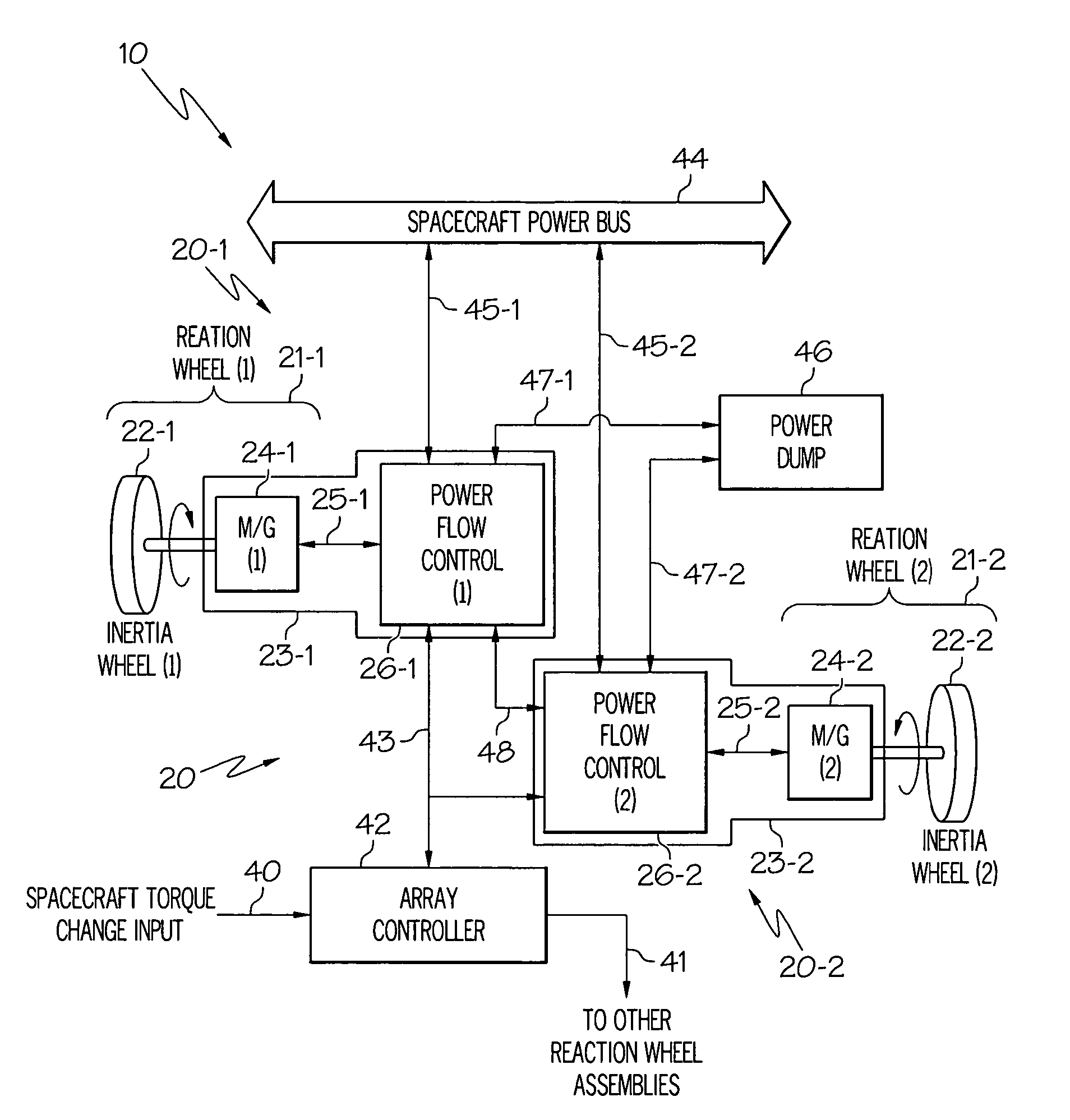
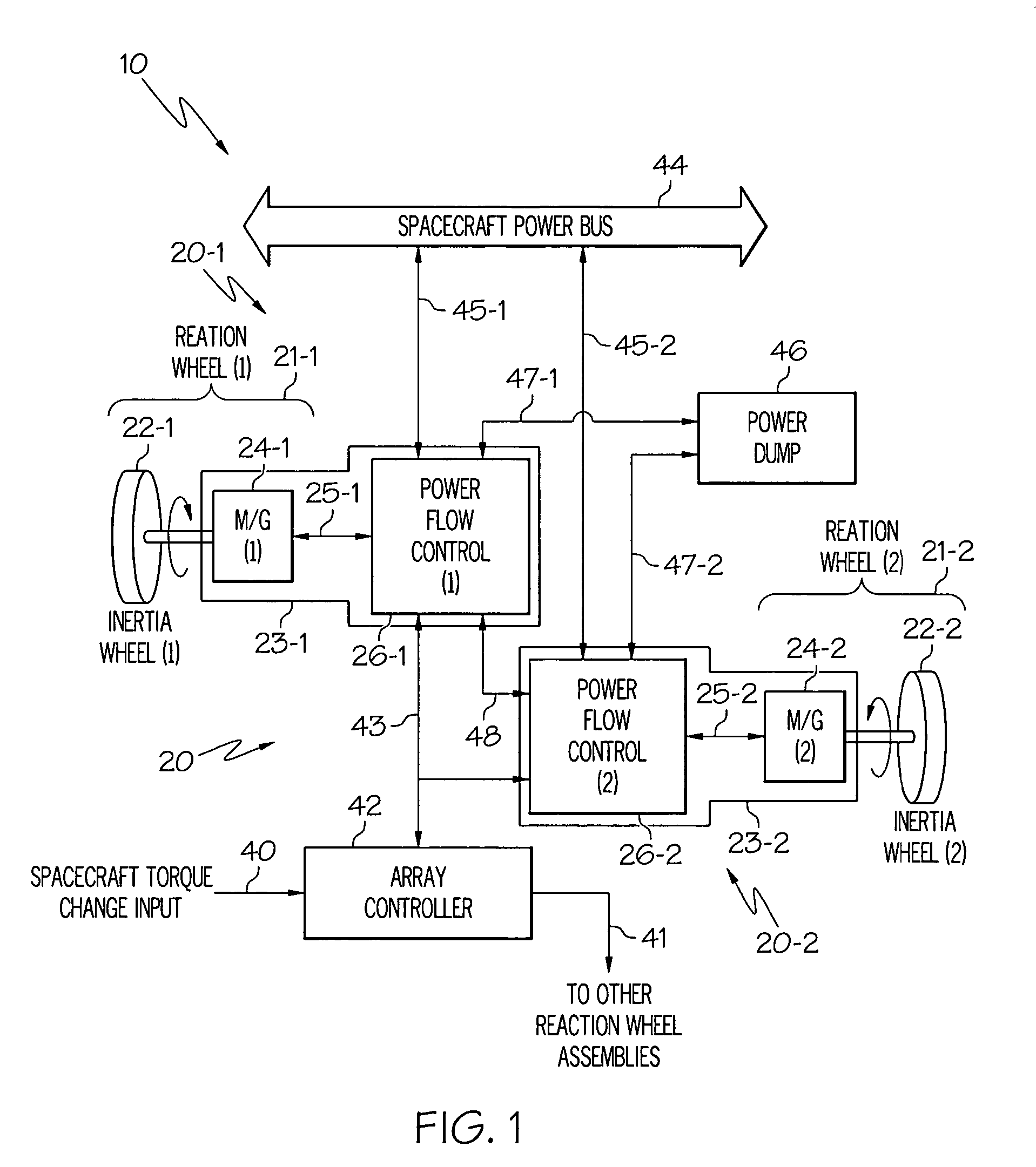
RWAs are less expensive and sometimes easier to implement but achieving high torque over the desired momentum range usually requires high peak power input and / or dissipation that is often beyond the capability of many spacecraft.
The power problems associated with conventional RWAs are more severe in smaller spacecraft where cost, power, weight, and reaction time are critical factors.

Method used


Image

  • High-torque, low power reaction wheel array and method
  • High-torque, low power reaction wheel array and method
  • High-torque, low power reaction wheel array and method

Examples


Embodiment Construction

[0013]The following detailed description is merely exemplary in nature and is not intended to limit the invention or the application and uses of the invention. Furthermore, there is no intention to be bound by any expressed or implied theory presented in the preceding technical field, background, brief summary or the following detailed description.

[0014]The invention uses one more reaction wheel than is mathematically necessary merely for producing the desired momentum change. This provides one or more mathematical degree of freedom for energy manipulation in addition to those needed merely for momentum manipulation via torque transfer to and from the spacecraft. For example, a single-axis array of wheels of the present invention uses at least two reaction wheels and a three axis array uses at least four reaction wheels, and so forth. The invention provides high steering torque and reduced peak spacecraft power drain (or dissipation) for spacecraft maneuvers by transferring energy d...


PUM


Abstract

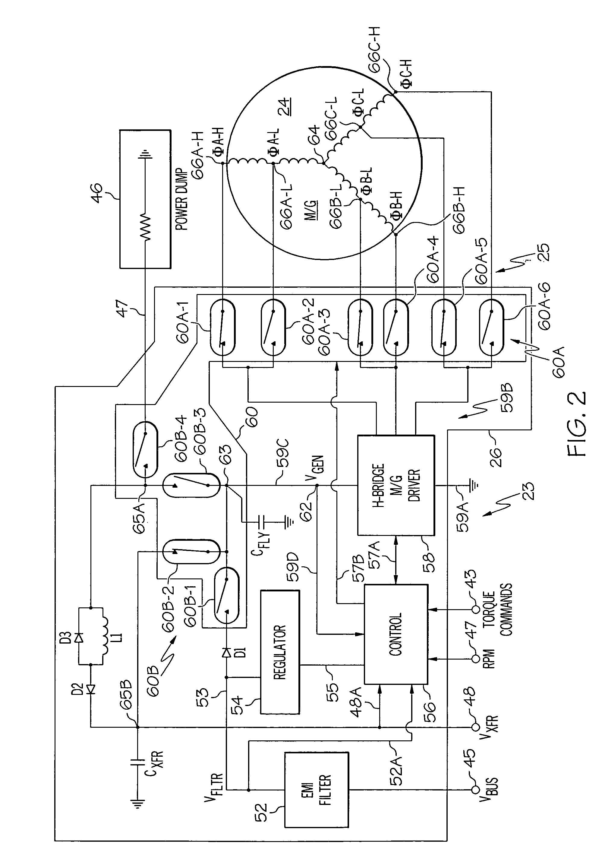
Methods and apparatus are provided for reaction wheel (RW) assemblies for spacecraft. The apparatus comprises a M / G coupled to an inertia wheel and a controller coupled to the M / G that, in response to commands it receives, couples power to or from an M / G of another RW assembly over a shared transfer connection (VXFR), so that one M / G acts as a generator powering another M / G acting as a motor. The controller compares generator voltage VGEN to the BEMF of the motor on VXFR and reconfigures a multi-winding M / G or steps-up the generated voltage to maintain VGEN>VXFR to maximize direct energy transfer from one RW to the other as long as possible. When VGEN declines sufficiently, the controller can couple the motor to the spacecraft power bus and / or the generator to a power dump so as to continue to provide the commanded torque if needed. Operation is automatic.

Description

TECHNICAL FIELD[0001]The present invention generally relates to controlled momentum transfer apparatus and methods, and more particularly controlled momentum transfer using two or more electrically coupled reaction wheels.BACKGROUND[0002]Modern spacecraft use control moment gyros (CMGs) and / or rotating inertia wheels to provide attitude control. Inertia wheels combined with motor generators (M / Gs) are commonly referred to as reaction wheels (RWs). Multiple RWs may be combined to form a reaction wheel array or assembly (RWA). In general multiple CMGs or RWs oriented in different directions are used. Angular momentum stored in rotating inertia wheels within the CMGs or RWAs is converted to torque which is exchanged with the spacecraft to change its attitude in space. Torque is the time derivative of angular momentum. Reaction wheels have also been proposed for energy storage in spacecraft, a separate function. Sometimes, RWAs have been used in a combined function wherein they provide ...

Claims


Application Information

Patent Timeline
Patent Type & Authority Patents(United States)
IPC IPC(8): B60L9/00B60L11/00
CPCB64G1/283B64G1/427
Inventor HART, ROBERT J.PECK, MASON A.
Owner HONEYWELL INT INC
Learn More