Rotary beverage filling machine for filling cans with a liquid beverage

a beverage and filling machine technology, applied in liquid handling, packaging goods, transportation and packaging, etc., can solve the problems of complex, time-consuming and laborious, and the removal of the rinsing cap after the rinsing and cleaning phase is a complex and expensive process, and the handling of the rinsing cap is particularly time-consuming and laborious

Inactive Publication Date: 2009-04-07
KHS GMBH
View PDF11 Cites 9 Cited by
  • Summary
  • Abstract
  • Description
  • Claims
  • Application Information

AI Technical Summary

Benefits of technology

[0020]An object of at least one possible embodiment is therefore to indicate a filling element equipped with a rinsing cap that essentially eliminates or minimizes the above disadvantages and is held in the sealed position so that leaks can be reliably prevented.SUMMARY

Problems solved by technology

The placement and fixing in position of the rinsing caps in preparation for the rinsing or cleaning phase as well as the removal of these rinsing caps after the rinsing and cleaning phase is a complex, expensive and time-consuming process.
Because the handling of the rinsing caps is particularly time-consuming and expensive when the related activities must be performed manually, numerous suggestions have been made in the past to automate these activities.
For cost-reduction reasons, the filling positions of can filling machines are therefore located very close together, which causes problems in the arrangement of automatically movable rinsing caps.
This geometric configuration of two rinsing caps on a carrier element results in a significant disadvantage of the device described in Japanese Patent No. 9-309593A, but also in all additional corresponding devices in which the rinsing caps are moved from a radially inner position into a radially outer position.
On the basis of these parameters, there is a force of up to 1500 N per rinsing cap, which in connection with the disadvantageous location of the points of the application of force can result in an elastic deformation of the rinsing cap fastening.
In practice, it is frequently observed that the seals of the rinsing caps sometimes lose some or all of their sealing function as a result of these plastic deformations, as a result of which the rinsing or cleaning fluid, which is under high pressure, escapes and contaminates the filling valve and / or the filling machine.
This escape of rinsing or cleaning fluid is generally considered a disadvantage.
Of course, this device overcomes the disadvantage of the unfavorable location of the points of the application of force, although the location of the receptacle elements on the circular arc of the midpoints of the filling valves is particularly disadvantageous, because the individual filling elements must, under some conditions, be located at an increased distance from one another.
A device of this type is also mechanically complex and expensive.

Method used


Image

  • Rotary beverage filling machine for filling cans with a liquid beverage
  • Rotary beverage filling machine for filling cans with a liquid beverage
  • Rotary beverage filling machine for filling cans with a liquid beverage

Examples


Embodiment Construction

[0030]Developments, advantages and potential applications of the invention will become apparent on the basis of the following description of the exemplary embodiments and of the accompanying drawing. All the characteristics described and / or illustrated are the object of the invention, individually or in any possible combination, regardless of their placement in the claims or the references between claims. The text of the claims is simultaneously incorporated by reference into the description.

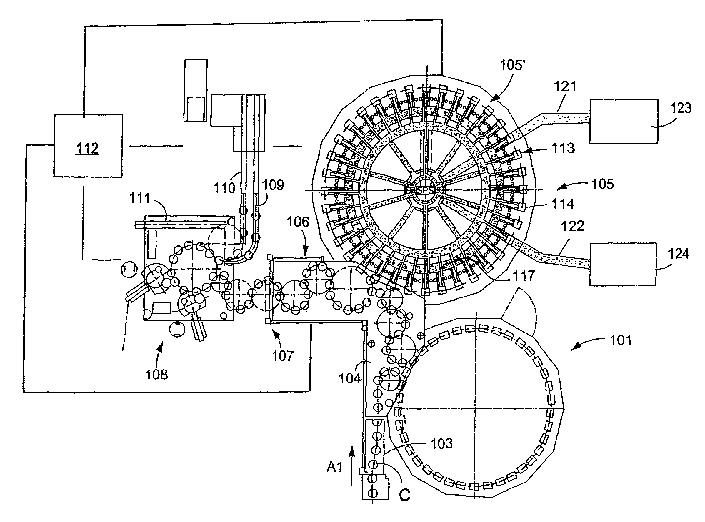
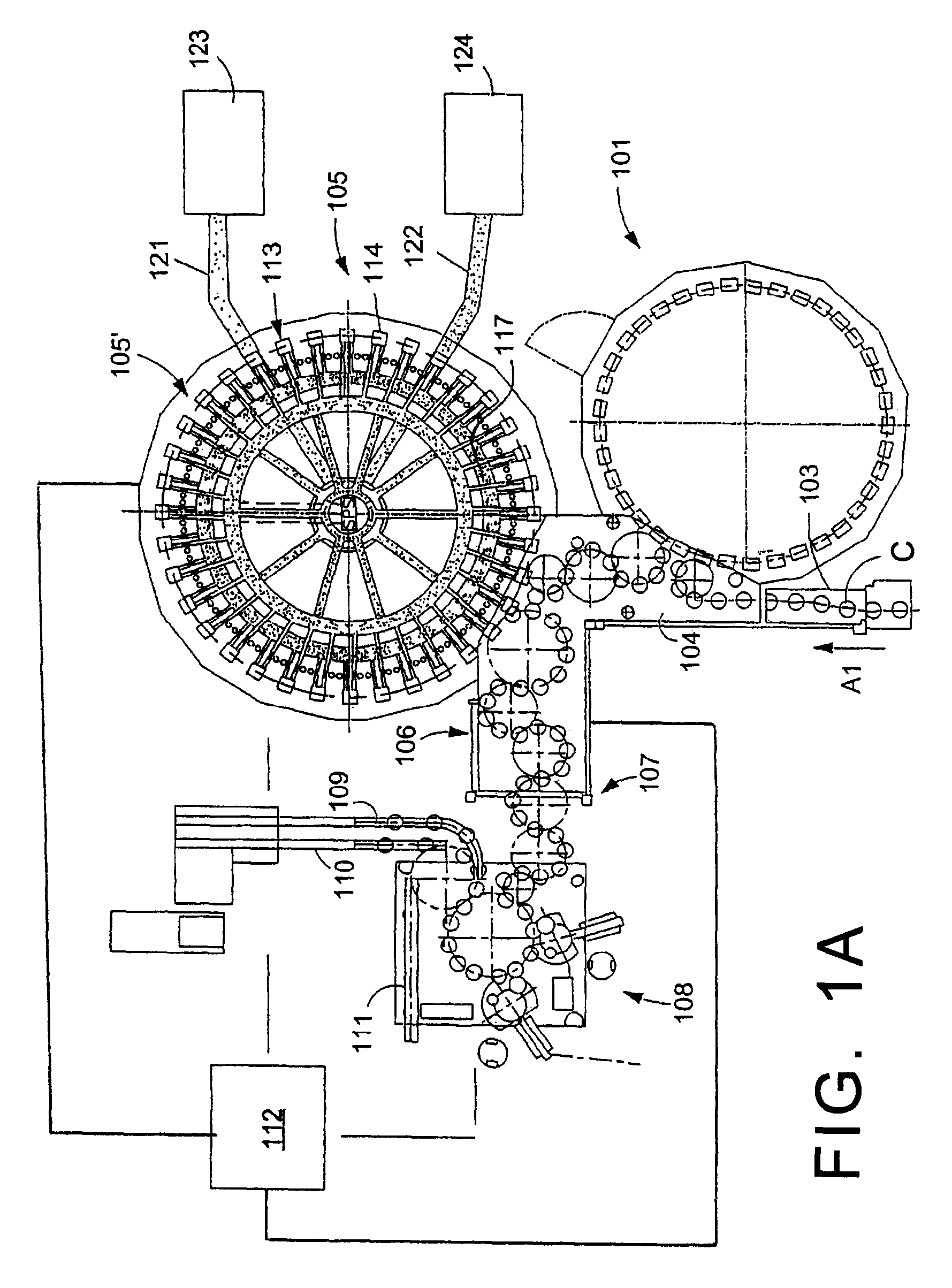
[0031]FIG. 1A shows schematically the main components of one possible embodiment example of a system for filling containers, specifically, a beverage can filling plant for filling cans C with at least one liquid beverage, in accordance with at least one possible embodiment, in which system or plant could possibly be utilized at least one aspect, or several aspects, of the embodiments disclosed herein.

[0032]FIG. 1A shows a rinsing arrangement or rinsing station 101, to which the containers, namel...


PUM

PropertyMeasurementUnit
diametersaaaaaaaaaa
diametersaaaaaaaaaa
pressuresaaaaaaaaaa

Abstract

A rotary beverage filling machine for filling cans with a liquid beverage. The rotary beverage filling machine comprises rinsing cap structures for closing the dispensing openings of the filling elements to permit cleaning of the filling elements.

Description

BACKGROUND[0001]1. Technical Field[0002]This application relates to a beverage filling machine for filling cans with a liquid beverage. This application further relates to a filling element with a rinsing cap which can be moved between a radially inner, non-engaged position and a radially outer, engaged position, whereby the rinsing cap is held and guided by radially inward guides, wherein the rinsing cap is additionally received and / or held in its engaged position by at least one receptacle. Advantageous developments of at least one possible embodiment are described herein below.[0003]2. Background Information[0004]Filling elements, in particular those for use on rotary-type filling machines, are known in an extremely wide variety of models. It is also known that these filling elements as well as the surfaces of the filling elements that come into contact with critical areas of the containers during the filling process can be cleaned and / or rinsed in a cleaning or rinsing phase wit...

Claims


Application Information

Patent Timeline
Patent Type & Authority Patents(United States)
IPC IPC(8): B65B3/04B65B43/50B67C3/02
CPCB67C3/004
Inventor BERNHARD, HERBERTJACOB, TIMO
Owner KHS GMBH
Why Eureka
Try Eureka