Rotary mixing device in molded packaging

a technology of rotary mixing and molded packaging, which is applied in the direction of rotary stirring mixers, transportation and packaging, and other chemical processes, can solve the problems of time-consuming cleaning and difficult use, and achieve the effect of preparing for printing or inking materials

Active Publication Date: 2009-04-07
VENUS DONALD W
View PDF30 Cites 19 Cited by
  • Summary
  • Abstract
  • Description
  • Claims
  • Application Information

AI Technical Summary

Benefits of technology

[0005]In an exemplary embodiment of the disclosure, a disposable and recyclable rotary mixing device is provided. The rotary mixing device consists of a polymeric shaft and one or more polymeric mixing discs. The components are preferably formed of the same material and are produced by molding the components in essentially a single plane. Moreover, the runners that provide the liquid polymer material to form the components of the rotary mixing device also serve as holding elements. Consequently, a one-piece, single shot molded unit is produced containing the components and the holding elements. The polymer material also preferably readily accepts printing or inking materials, allowing for instructions, promotional information and the like to be applied directly to the molded product. This combination eliminates the need for additional packaging material.
[0006]When usage is desired, the rotary mixing device can be easily assembled by the end user. The polymeric shaft and one or more of the polymeric discs are detached for the runners, which hold the molded components together. The shaft can then be inserted or joined with a motor, such as a drill motor, to produce rotary motion. Upon completion of usage, the entire assembled unit can be easily discarded. This avoids any additional clean-up steps that can be time-consuming and / or expensive.

Problems solved by technology

These devices are three-dimensional in structure and are, in many instances, difficult to use and time consuming to clean.

Method used


Image

  • Rotary mixing device in molded packaging
  • Rotary mixing device in molded packaging
  • Rotary mixing device in molded packaging

Examples


Embodiment Construction

[0020]It should, of course, be understood that the description and drawings herein are merely illustrative and that various modifications and changes can be made in the structures disclosed without departing from the spirit of the disclosure. Like numerals refer to like parts throughout the several views.

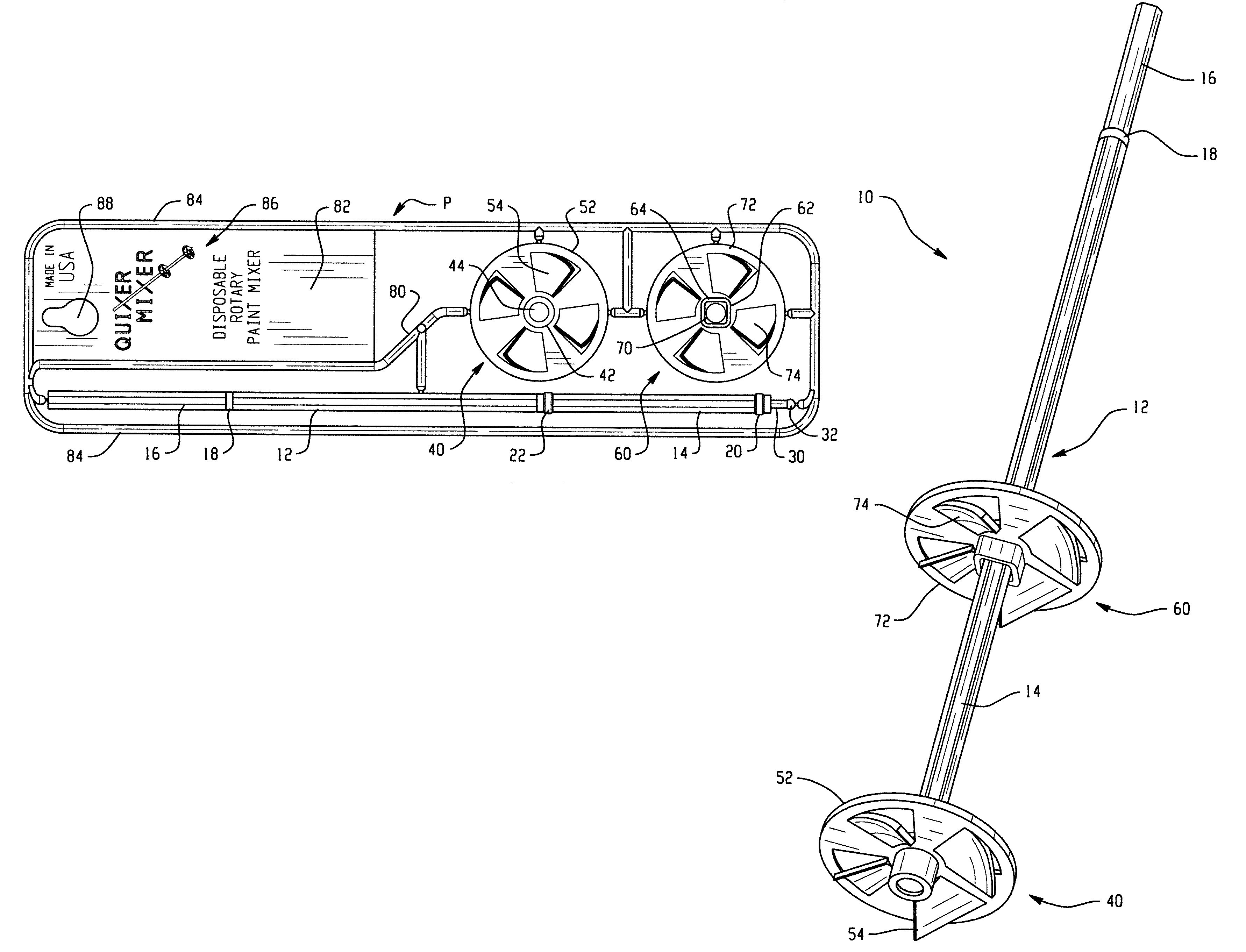
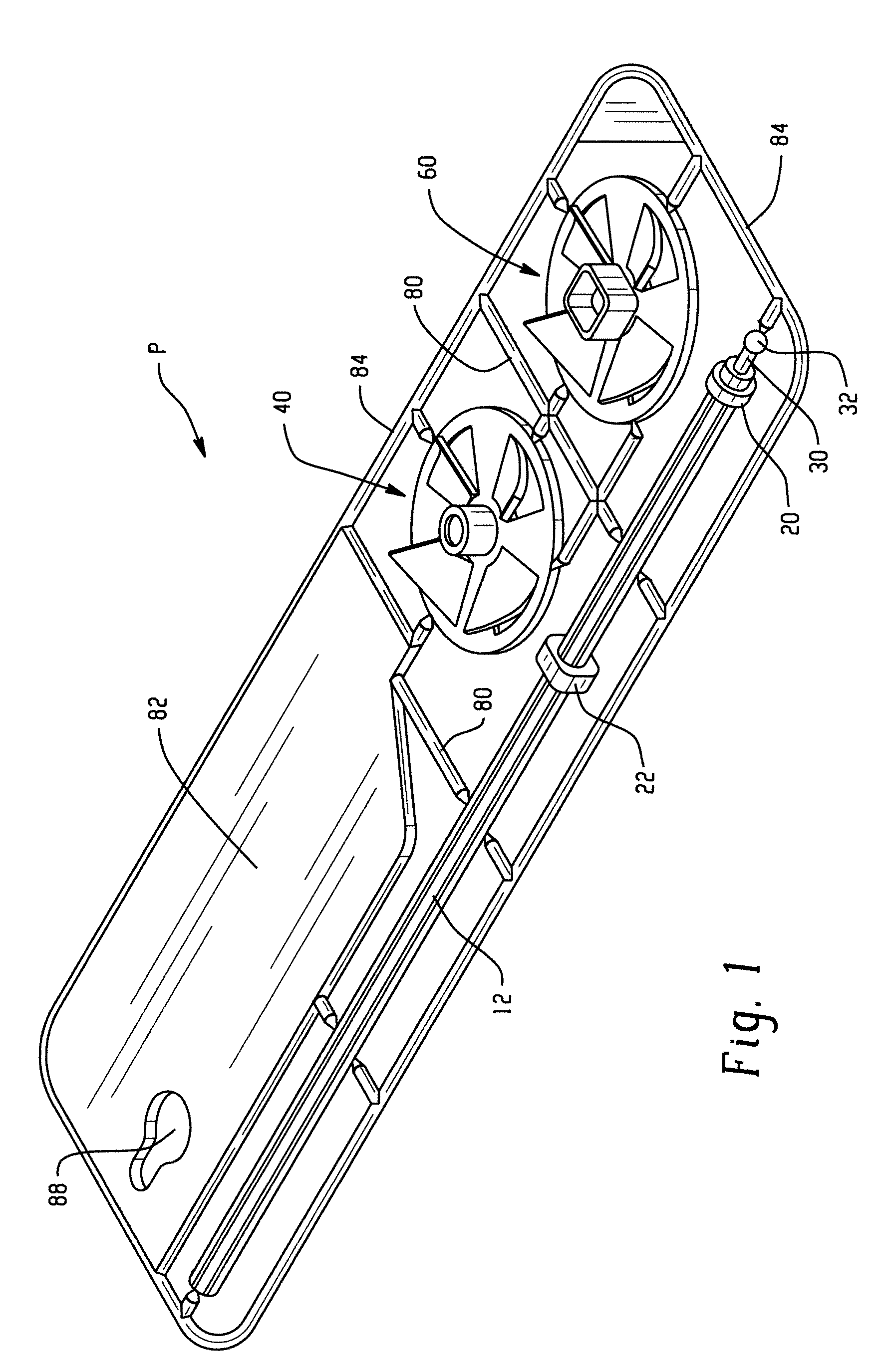
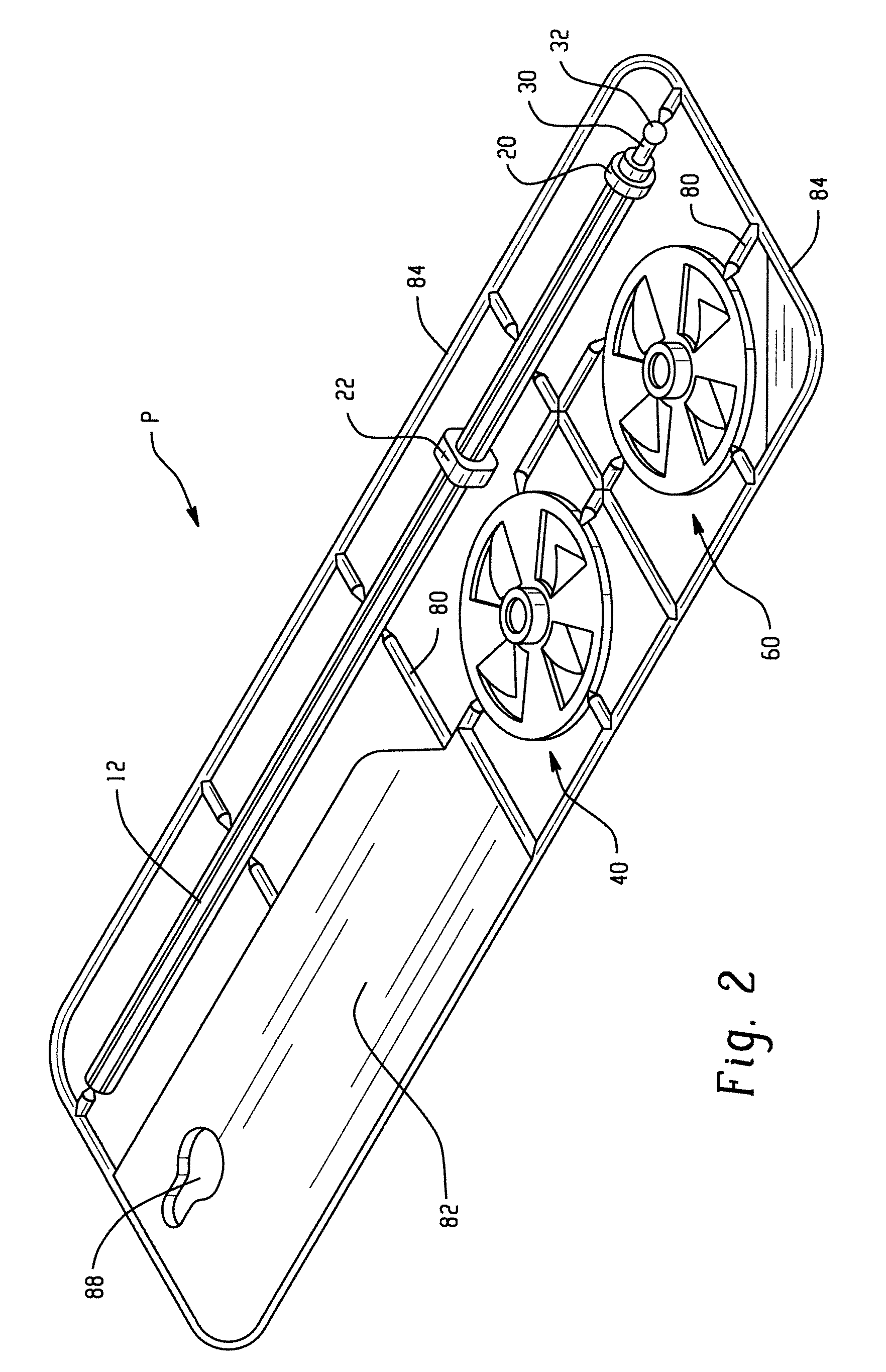
[0021]Referring now to the drawings, wherein the showings illustrate a preferred embodiment of the development only and are not intended to limit same, FIGS. 1 and 2 show the packaging P of a rotary mixer 10 prior to assembly in accordance with one embodiment of the disclosure.

[0022]With reference to FIG. 3, the individually components of the rotary mixer 10 are depicted prior to assembly. The rotary mixer 10 is formed by the combination of a shaft 12, a first or lower mixing member 40, and a second or upper mixing member 60. As will be described more fully below, depending on the mixing application and the goals of the user, the lower mixing member 40 and the upper mixing element 6...


PUM

PropertyMeasurementUnit
shapeaaaaaaaaaa
cross-sectional shapeaaaaaaaaaa
timeaaaaaaaaaa

Abstract

The present disclosure relates to a rotary mixing device that is easy to produce, assemble, use and dispose of. The device comprises a shaft, and at least one mixing member. The shaft and mixing member are formed of the same composite material and are produced by molding the components in essentially a single plane. Moreover, the runners that provide the liquid polymer material to form the components of the rotary mixing device also serve as holding elements. Consequently, a one-piece, single shot molded unit is produced containing the components and the holding elements.

Description

CROSS REFERENCE TO RELATED APPLICATIONS[0001]This application claims priority from U.S. Provisional Patent Application Ser. No. 60 / 486,075 filed Jul. 10, 2003 and U.S. Provisional Patent Application Ser. No. 60 / 569,999 filed May 11, 2004, both of which are incorporated herein by reference.BACKGROUND[0002]The present disclosure relates to the art of rotary mixing devices. More particularly, the disclosure is directed to a rotary mixer for efficient mixing and stirring liquids, compounds, particulate matter, and other materials. The disclosure is also directed to a rotary mixer which is easy to produce, assemble and utilize. Optionally, the rotary mixer is also readily disposable and recyclable upon completion of use thereby minimizing cleanup time and expense.[0003]In this regard, rotary mixing devices, such as rotary paint mixers and cement mixers, are well known and are readily utilized by commercial contractors and homeowners. These rotary mixing devices are designed to allow the ...

Claims


Application Information

Patent Timeline
Patent Type & Authority Patents(United States)
IPC IPC(8): B01F7/26B01F27/93B29C45/00
CPCB01F7/001B01F7/00466B01F13/002B29C45/006B01F2215/005B29C2045/0086Y10S366/605B01F27/071B01F27/1152B01F33/5011B01F2101/30
Inventor VENUS, DONALD W.
Owner VENUS DONALD W
Why Eureka
Try Eureka