Vacuum kneading method with the introduction of oxygen and the device used to carry out said method

a vacuum kneading and oxygen-injected technology, which is applied in the directions of dough mixing/kneading machines, food preservation, baking, etc., can solve the problems of two kneading phases, reduce the oxidation of the improvers used by bakers, and not be able to control the development of the bubble structure in the bread dough

Inactive Publication Date: 2009-04-07
VMI INC
View PDF27 Cites 3 Cited by
  • Summary
  • Abstract
  • Description
  • Claims
  • Application Information

AI Technical Summary

Benefits of technology

[0044]Thus the supply means open out outside the passage of the rotor blades and are easily accessible.

Problems solved by technology

However, this method does not make it possible to control the development of the bubble structure in the bread dough.
However, the creation of a partial vacuum removes the air, which reduces the oxidation of the improvers used by bakers (ascorbic acid or potassium bromate) for intensifying the formation of the gluten lattice and, stabilising the structure of the bubbles.
This method has the drawback of requiring two kneading phases, including one phase under air overpressure which is difficult to achieve with normal kneading means.

Method used


Image

  • Vacuum kneading method with the introduction of oxygen and the device used to carry out said method
  • Vacuum kneading method with the introduction of oxygen and the device used to carry out said method
  • Vacuum kneading method with the introduction of oxygen and the device used to carry out said method

Examples


first embodiment

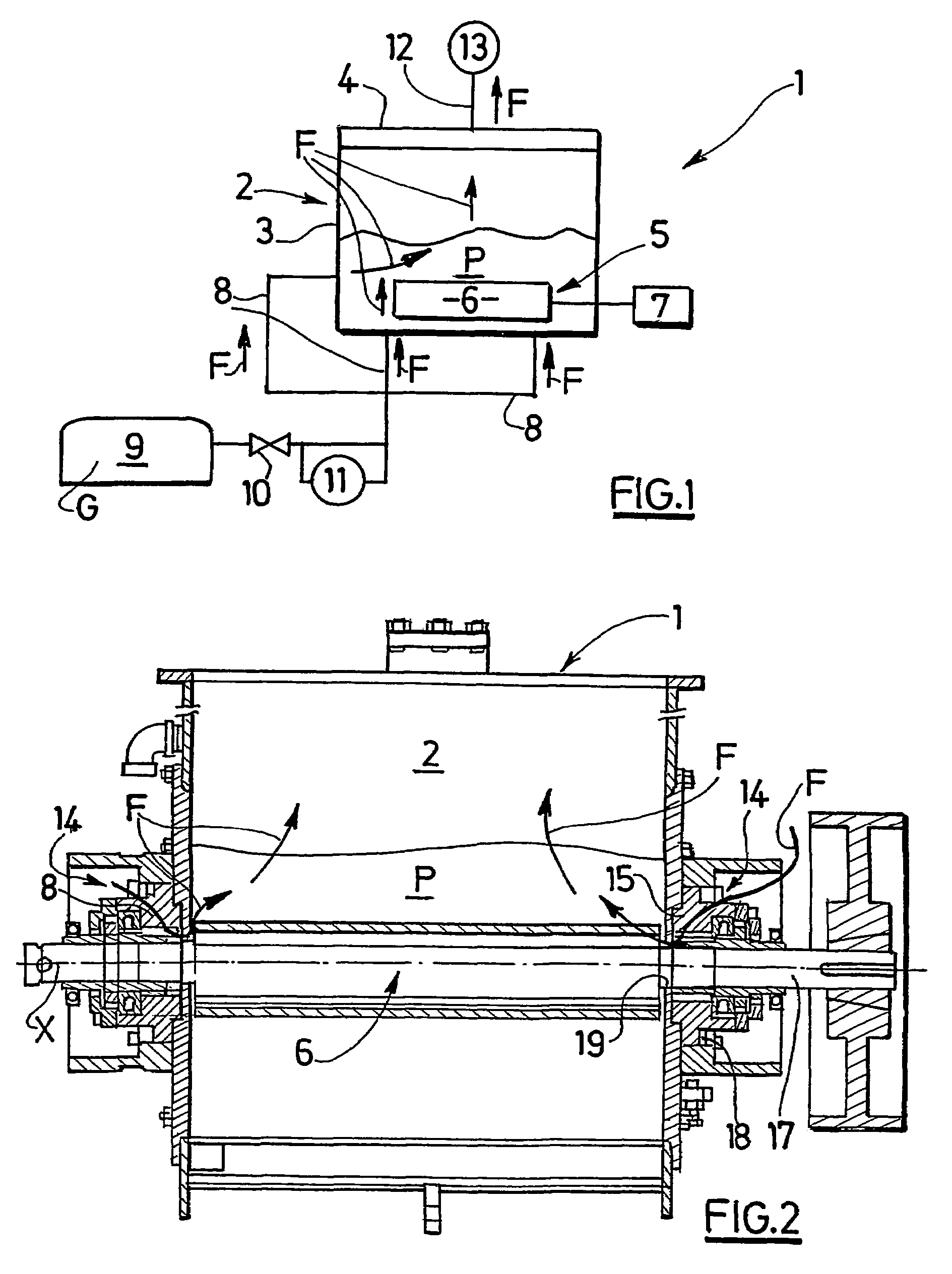
[0076]In a first embodiment, with reference to FIGS. 2 to 4, the axis X of the rotor 6 is horizontal and the fixing and sealed guidance of the rotor 6 with respect to the said vessel 3 are achieved by means of bearings 14.

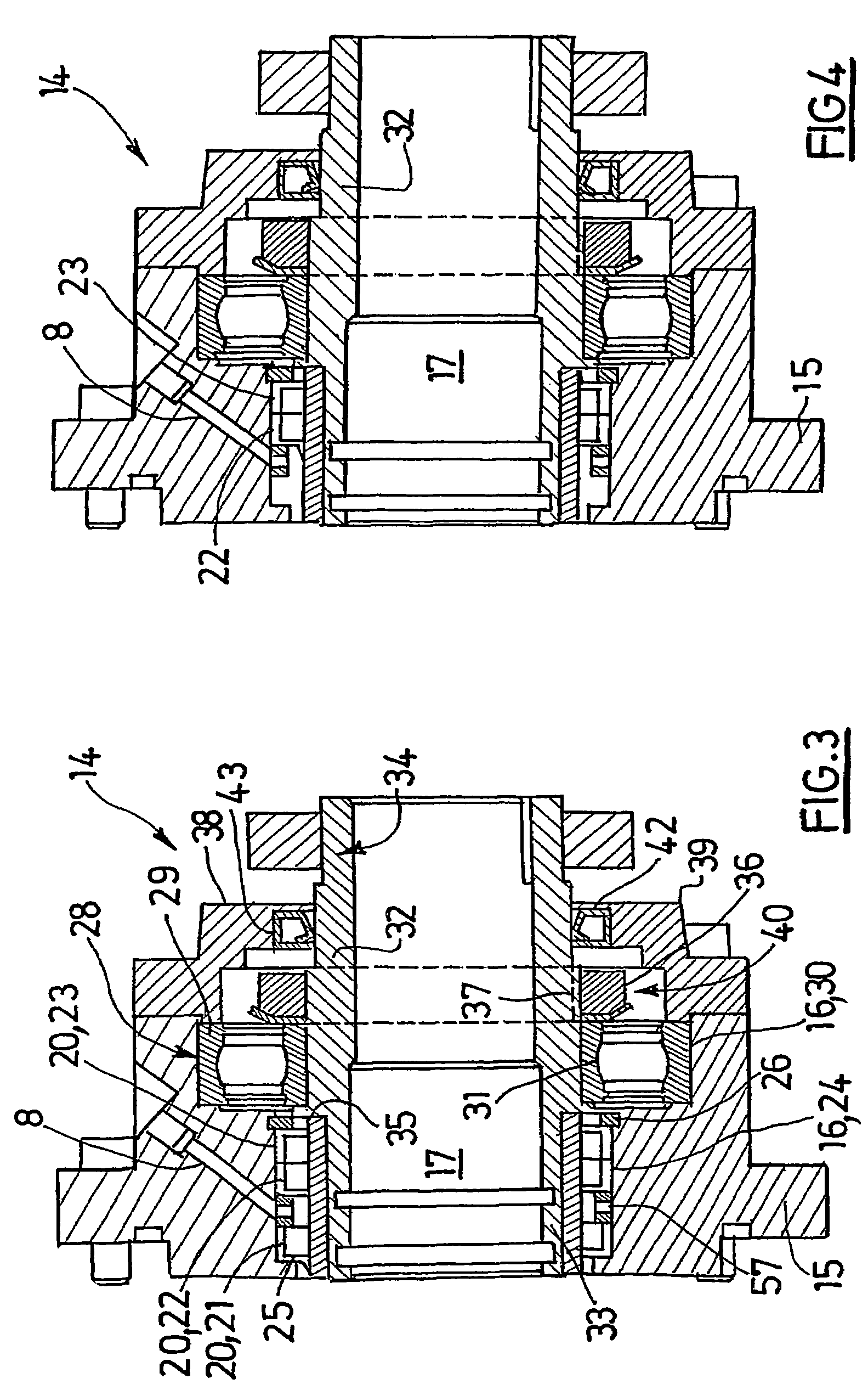
[0077]One of the bearings 14 is now described in detail, assuming the two bearings to be identical.

[0078]The bearing 14 comprises a bearing body 15 which has a through central recess 16 called a seat, having symmetry of revolution, and in which an end part 17 of the rotor 6 is inserted.

[0079]The bearing body 15 is fixed to a side wall of the vessel 3 on the external side, by means of removable fixing means 18 such as screws regularly distributed over the circumference of the bearing body 15.

[0080]The bearing body 15 is fixed in line with an opening 19 formed in the said side wall of the vessel 3, so that the axis of revolution of the seat 16 coincides with the rotation axis X of the rotor 6.

[0081]The bearing 14 is designed to provide a total seal of the inside of t...

second embodiment

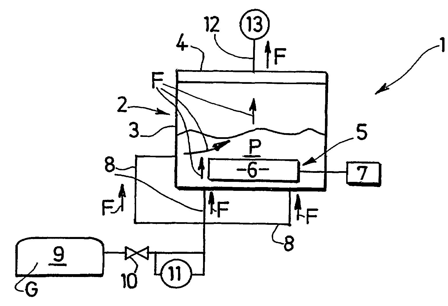
[0113]In a second embodiment, with reference to FIG. 5, the device is such that the axis X of the rotor 6 is horizontal and the vessel 3 is asymmetric with respect to a vertical plane P1 passing through the rotation axis X of the rotor.

[0114]The vessel comprises a first substantially vertical side wall 45 and a second side wall 46 inclined by a given angle to the vertical.

[0115]The curved vessel bottom connects the first wall 45 to the second side wall 46, so that the vessel 3 comprises, on the same side as the second side wall 46, a space 47 opening out towards the top in the form of a crescent.

[0116]This space 47 is situated between the second side wall 46 and the path followed by the free end of the rotor 6 blades. This path is represented by the curve C in FIG. 5.

[0117]The gas supply means 8 open out in the said space 47, outside the passage area of the rotor 6 blades, and are thus easily accessible.

[0118]A particular arrangement of the walls 45, 46 of the vessel 3 is described ...


PUM

PropertyMeasurementUnit
pressureaaaaaaaaaa
pressureaaaaaaaaaa
absolute pressureaaaaaaaaaa

Abstract

The invention relates to a method of kneading dough in order to produce bread or similar products. According to the invention, the dough ingredients are introduced into a chamber and all of said ingredients are subsequently kneaded. The inventive method is characterised in that it comprises: a vacuum phase during which a vacuum is applied in the chamber; and one or more phases involving the introduction of gas, during which a gas containing oxygen is introduced into the chamber. The aforementioned vacuum phase continues more or less throughout the entire kneading phase, with at least one part of each introduction phase taking place simultaneously with the kneading phase. The invention also relates to a device that is used to carry out said method.

Description

CROSS-REFERENCE TO RELATED APPLICATIONS[0001]This application is a National Phase Application of PCT / FR02 / 03542, which claims priority to French Patent Application No. 0113521, filed Oct. 19, 2001, entitled “Vacuum Kneading Method with the Introduction of Oxygen and the Device Used to Carry Out Said Method,” both of which are incorporated by reference herein.BACKGROUND OF THE INVENTION[0002]The invention concerns a method of kneading dough for making bread or similar products and a device for implementing the said method.[0003]The document EP-A-0 246 768 describes a method and apparatus for kneading bread dough in an oxygen-enriched atmosphere. To this end, oxygen or oxygen-enriched air is introduced into the chamber of the apparatus contained in the dough before or during kneading. The atmosphere in the chamber is then discharged through a discharge pipe. This addition of oxygen promotes the action of the ascorbic acid, used as a single improving product (known as an improver in th...

Claims


Application Information

Patent Timeline
Patent Type & Authority Patents(United States)
IPC IPC(8): A21D2/00A21C1/00A21C1/06A21C1/10A21C1/14A21D8/02B01F23/30
CPCA21C1/006A21C1/06A21C1/10A21C1/1495A21D8/025B01F13/06B01F2003/063B01F2015/00097B01F23/34B01F33/70B01F2035/3512
Inventor FISSON, GERARDJAUNET, LAURENTVANNIER, GUILLAUME
Owner VMI INC
Why Eureka
Try Eureka