Binocular display with improved contrast uniformity

a binocular display and uniform contrast technology, applied in the field of binocular video displays, can solve the problems of user discomfort, headache, and inability to use the binocular display for extended periods of time, and achieve the effects of improving optical contrast uniformity, reducing headaches, eye strain, and other discomforts

Active Publication Date: 2009-04-07
TDG ACQUISITION COMPANY
View PDF11 Cites 25 Cited by
  • Summary
  • Abstract
  • Description
  • Claims
  • Application Information

AI Technical Summary

Benefits of technology

[0006]One or more of the preferred embodiments of this invention feature a binocular display with improved optical contrast uniformity that overcomes this problem. Asymmetric directionally sensitive contrast can be balanced between the left and right eyes of users, not only for users having a particular interpupillary distance (IPD) but also for users having different interpupillary distances, which are more or less than the average interpupillary distance intended for the binocular display. Reduced eyestrain, headaches, and other discomforts, as well as the possibility for extended viewing of binocular displays, are among the benefits of this invention.
[0013]In accordance with yet another aspect of the invention, a binocular display includes left and right display screens mounted within a viewing device for viewing by corresponding left and right eyes of users. Both of the display screens have a predetermined top to bottom orientation, such as by factory specification, and exhibit a similar directionally sensitive contrast that varies asymmetrically with respect to a direction of peak contrast. One of the left and right display screens is rotated top to bottom with respect to the other of the display screens within the viewing device so that the asymmetric contrasts are oriented in different directions with respect to the left and right eyes of the users for reducing differences in contrast presented to the left and right eyes of the users over a range of different interpupillary distances.
[0014]Yet another aspect of the invention features a binocular display including first and second display screens mounted within a viewing device having first and second eyeboxes within which the respective first and second display screens are visible to users. The first and second display screens have first and second viewing axes directed toward the first and second eyeboxes. Each of the first and second display screens exhibits a direction of peak contrast that is inclined to the respective first and second viewing axes. The first display screen is oriented with respect to the second display screen so that the directions of peak contrast extend in different directions with respect to the first and second viewing axes to reduce contrast variations apparent between the different eyes of the users over a range of interpupillary distances.
[0016]The directional contrast of the display screens can vary asymmetrically within both (a) a lateral plane that includes the viewing axes of the two displays and (b) an orthogonal sagittal plane. If the directional contrast is similar between the left and right display screens, directional contrast asymmetries within the lateral plane can be balanced between the left and right eyes of users over a range of interpupillary distances by rotating one of the display screens with respect to the other. If the directional contrast is different between the left and right display screens, the display screens can be paired so that the directional contrast asymmetries within the lateral plane can be at least partially balanced between the left and right eyes of users. Directional contrast asymmetries in the sagittal plane of matching left and right display screens, which are generally not imbalanced by variations in interpupillary distances, can be subject to imbalance by relatively rotating the two display screens. However, the left and right display screens can be relatively translated in the direction of the sagittal plane to reduce the imbalance.

Problems solved by technology

If one of the user's eyes receives an image that has perceptively greater contrast than the image received by the user's other eye, the user may experience visual discomfort, headaches, or the like, and as a result, may be unable to use the binocular display for extended periods of time.
Moreover, the deviation from optimal contrast in some display screens is not symmetrical about the optimal viewing angle.
It can now be appreciated that if the known binocular displays are set to produce equal contrast for an average interpupillary distance of, say, 61 millimeters, deviations from this spacing may not only produce reduced contrast but may also produce unequal changes in contrast for the left and right eyes, resulting in the physiological discomfort described above.

Method used


Image

  • Binocular display with improved contrast uniformity
  • Binocular display with improved contrast uniformity
  • Binocular display with improved contrast uniformity

Examples


Embodiment Construction

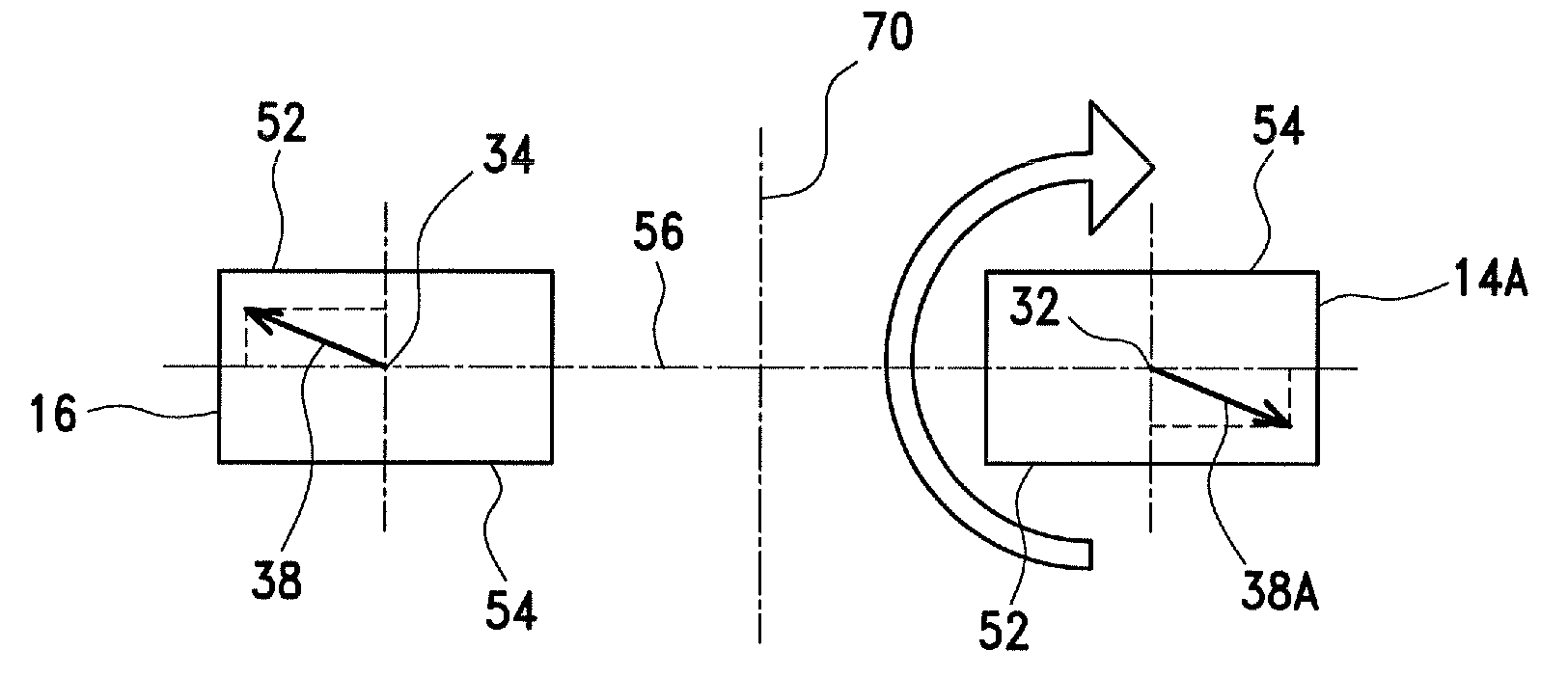
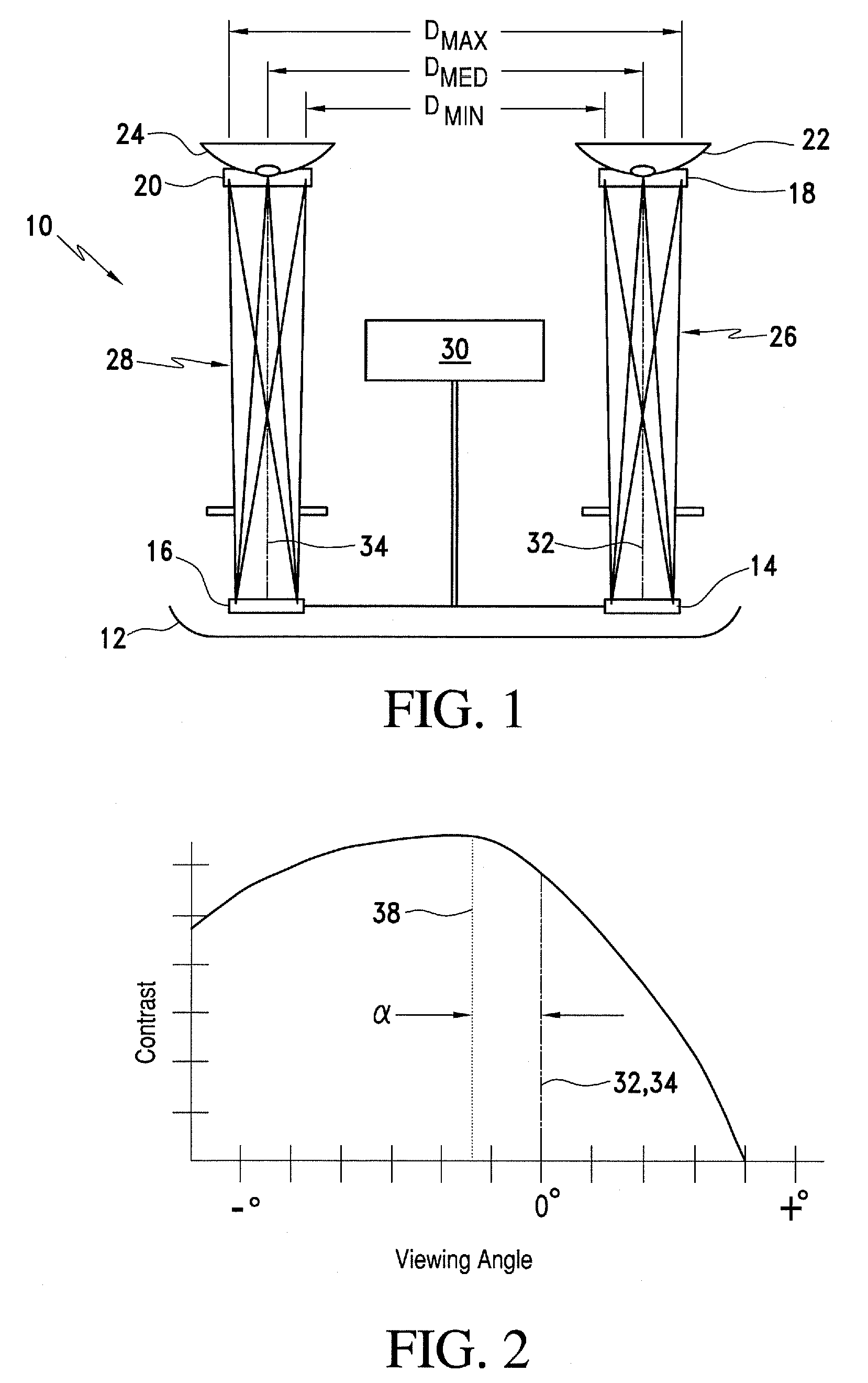
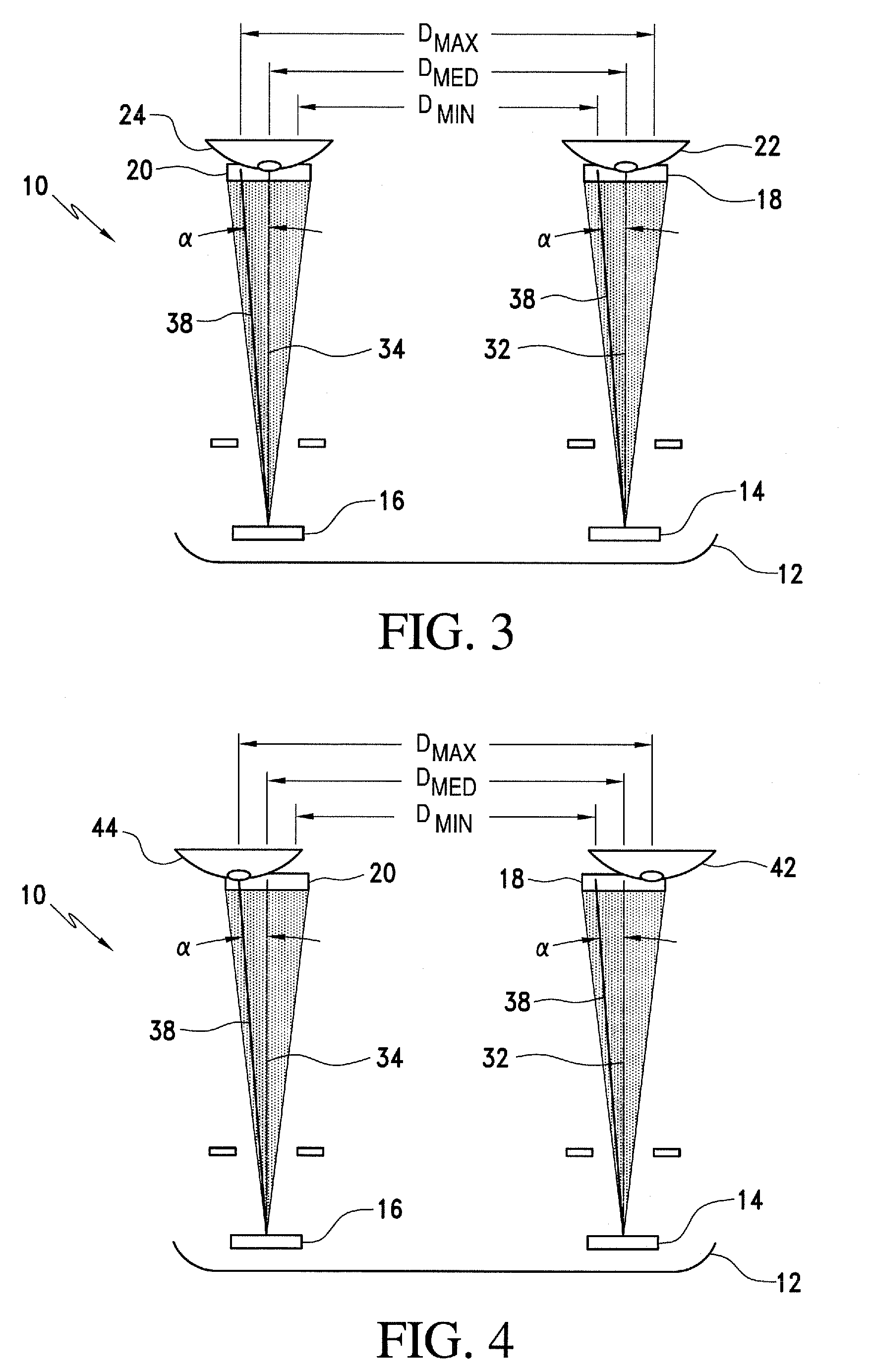
[0026]A binocular display 10 is depicted in FIG. 1 for purposes of reference. Within a common housing 12, left and right display screens 14 and 16 are visible within left and right eyeboxes 18 and 20 to left and right eyes 22 and 24 of a user. Optical systems 26 and 28 preferably include focusing optics (not shown) for producing magnified virtual images of the display screens 14 and 16 visible within the eyeboxes 18 and 20.

[0027]The display screens 14 and 16 are preferably compact high-resolution image generators capable of producing real images in a still or moving form containing more information than can be normally discerned by the human eye without magnification. Backlit liquid crystal displays (LCDs) are preferred for these purposes, such as Kopin 230K CyberDisplays PN#KCD-QDLF-M from Kopin Corporation of Massachusetts mounted with a fixed interpupillary distance of 63.5 mm and a 24 degree diagonal field of view through a conventional optical lens system. However, a variety of...


PUM


Abstract

A binocular display deals with an optical contrast imbalance problem between display screens manifest over a range of interpupillary distances by orienting contrast asymmetries between the display screens in opposite directions.

Description

FIELD OF THE INVENTION[0001]This invention relates generally to binocular video displays and, more particularly, to such displays with improved optical contrast uniformity compared with existing devices that exhibit optical contrast irregularities.BACKGROUND OF THE INVENTION[0002]Conventional binocular displays present images to the left and right eyes of a user as created by left and right display screens. Optics relay images of the display screens, generally as virtual images, to the user's eyes. Such binocular displays are used in a wide variety of applications including, head, hand, table, or otherwise mounted displays for reproducing still or moving images in monoscopic or stereoscopic form.[0003]One characteristic of such binocular displays that contributes or detracts from the comfort of the user is the relative optical contrast presented to the user's eyes from left and right display screens. If one of the user's eyes receives an image that has perceptively greater contrast ...

Claims


Application Information

Patent Timeline
Patent Type & Authority Patents(United States)
IPC IPC(8): G02B27/14G09G5/00
CPCG02B23/18G02B27/0172H04N13/0033H04N13/044G02B2027/0118G02B2027/0132H04N2213/002H04N13/144H04N13/344
Inventor TRAVERS, PAUL J.
Owner TDG ACQUISITION COMPANY
Why Eureka
Try Eureka