Rules engine for managing virtual logical units in a storage network

a storage network and rule engine technology, applied in the field of storage area networks, can solve the problems of increasing complexity, time-consuming, and difficult to determine the proper status of a virtual volume, and achieve the effect of efficient and accurate management and efficient management of the state of virtual targets

Active Publication Date:
View PDF1 Cites 21 Cited by
  • Summary
  • Abstract
  • Description
  • Claims
  • Application Information

AI Technical Summary

Benefits of technology

[0018]In accordance with embodiments, systems and methods are provided to efficiently manage the state of virtual targets. The core functionality of virtual target state maintenance is centralized to provide efficient and accurate management. One or more rules engines can provide proper state and status information for a virtual target after an event associated with one or more members of the virtual target is detected.

Problems solved by technology

More particularly, the management of raw data storage is becoming more cumbersome and difficult as more companies and individuals are faced with larger and larger amounts of data that must be effectively, efficiently, and reliably maintained.
As storage switches increase virtualization options, the management of virtual targets becomes an increasingly complex operation.
Determining the proper status for a virtual volume becomes more difficult and time-consuming as the complexity in provisioned virtual volumes increases.
Traditional techniques of coding each possible scenario to determine the resulting outcome can become impractical in today's fast-paced environment.
Initially developing a representation of every scenario can be very time-consuming.
Furthermore, any changes to the volume for which the code is applicable may require re-coding which can be impractical in today's flexible environment where volume definitions can easily be modified.

Method used


Image

  • Rules engine for managing virtual logical units in a storage network
  • Rules engine for managing virtual logical units in a storage network
  • Rules engine for managing virtual logical units in a storage network

Examples


Embodiment Construction

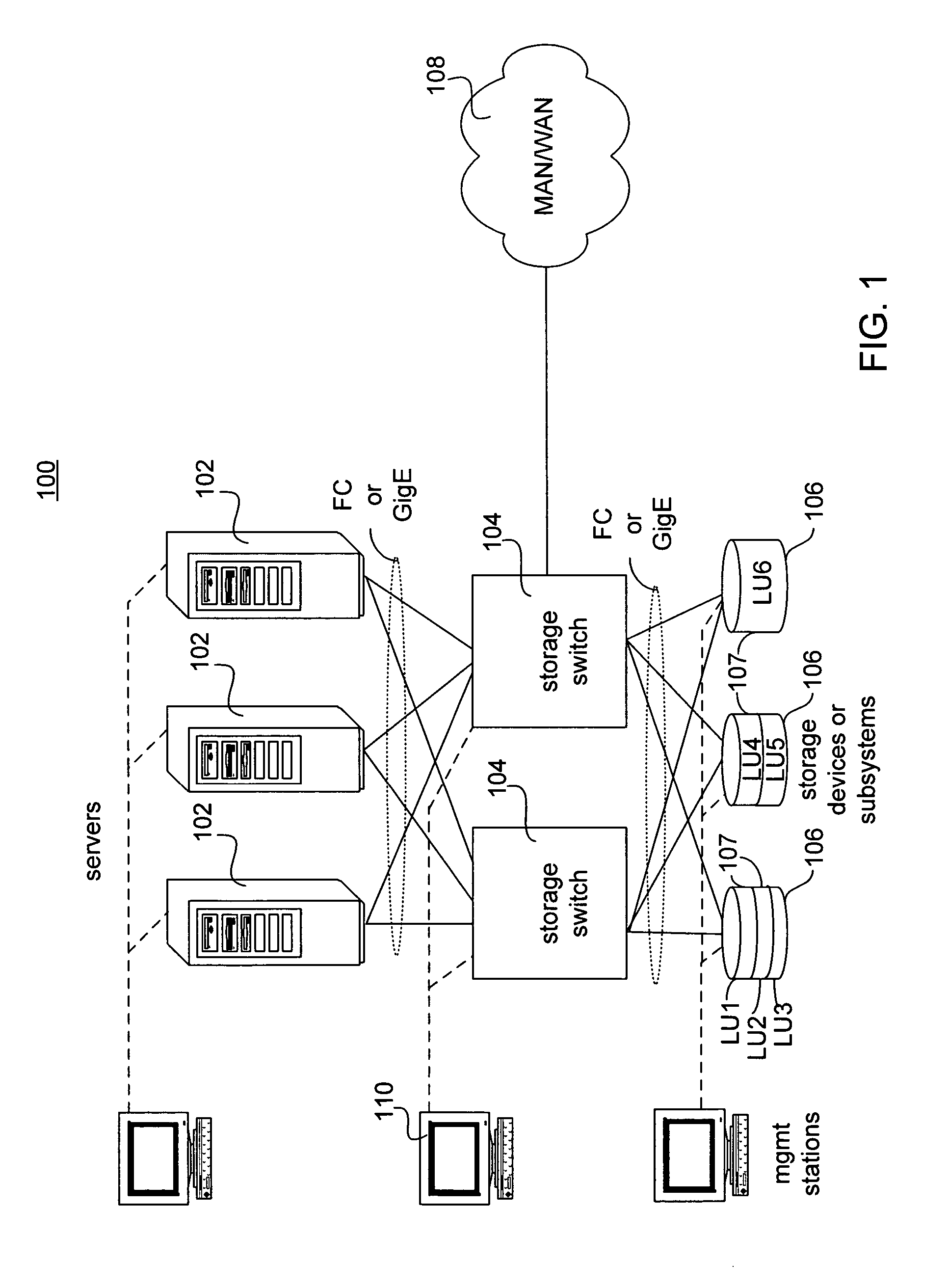
[0065]An exemplary system 100 including a storage switch in accordance with one embodiment is illustrated in FIG. 1. System 100 can include a plurality of initiating devices such as servers 102. It will be appreciated that more or fewer servers can be used and that embodiments can include any suitable physical initiator in addition to or in place of servers 102. Although not shown, the servers could also be coupled to a LAN. As shown, each server 102 is connected to a storage switch 104. In other embodiments, however, each server 102 may be connected to fewer than all of the storage switches 104 present. The connections formed between the servers and switches can utilize any protocol, although in one embodiment the connections are Fibre Channel or Gigabit Ethernet (carrying packets in accordance with the iSCSI protocol). Other embodiments may use the Infiniband protocol, defined by the Infiniband Trade Association, or other protocols or connections.

[0066]In some embodiments, one or ...


PUM


Abstract

A rules engine is provided to enhance management capability in storage area networks and particularly within storage switches. Resulting state and status information for virtual logical units can be maintained in a database. The database can be indexed according to the current state and / or status of members of a virtual logical unit. When an event associated with a physical target of a virtual logical unit is detected, the current state and status of members of the virtual logical unit can be determined. The current state and status information can be maintained in dynamic state and status indicator. The current state and status information can be used to identify a corresponding entry in the rules database. From the rules database, the proper resulting status and / or state of the members and / or the virtual logical unit can be determined.

Description

CROSS-REFERENCE TO RELATED APPLICATIONS[0001]The following applications are cross-referenced and incorporated by reference herein in their entirety:[0002]U.S. patent application Ser. No. 10 / 931,504, entitled MULTI-CHASSIS, MULTI-PATH STORAGE SOLUTIONS IN STORAGE AREA NETWORKS, filed concurrently;[0003]U.S. patent application Ser. No. 10 / 833,438, entitled PROACTIVE TRANSFER READY RESOURCE MANAGEMENT IN STORAGE AREA NETWORKS, filed Apr. 28, 2004;[0004]U.S. patent application Ser. No. 10 / 051,321, entitled STORAGE SWITCH FOR STORAGE AREA NETWORK, filed Jan. 18, 2002;[0005]U.S. patent application Ser. No. 10 / 051,396, entitled VIRTUALIZATION IN A STORAGE SYSTEM, filed Jan. 18, 2002; and[0006]U.S. patent application Ser. No. 10 / 050,974, entitled POOLING AND PROVISIONING STORAGE RESOURCES IN A STORAGE NETWORK, filed Jan. 18, 2002, now U.S. Pat. No. 6,976,134, issued Dec. 13, 2005.BACKGROUND OF THE INVENTION[0007]1. Field of the Invention[0008]The present invention relates generally to stora...

Claims


Application Information

Patent Timeline
Patent Type & Authority Patents(United States)
IPC IPC(8): G06F13/00
CPCG06F17/30985G06F16/90344
Inventor GANDHI, SHREYAS P.
Why Eureka
Try Eureka